
Technical Specs

© 2022 Smart Wires Inc. Page 3 of 4
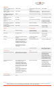
Electrical
Maximum Voltage Injection at
50 Hz or 60 Hz
(1)
± 5660 V RMS
Injection Mode 2-Hour Current
Rating
(5,6)
2160 A RMS
Minimum Injection Voltage at
50 Hz or 60 Hz
(2,3)
± 566 V RMS
Maximum Rate of Change of
Frequency (RoCoF) Withstand
2 Hz/s for up to 0.5 s
and 1 Hz/s for up to 1 s
Max Ramp Time from 0% to
90% of Maximum Injection
Voltage
(4)
200 ms
Maximum Corona-Free Voltage
550 kV RMS line-to-line
Minimum Current for
Monitoring
(5)
50 A RMS
Power Source
Powered by line current
Minimum Current for
Injection
(5)
100 A RMS
Operational Frequency Range
47.00 Hz to 52.00 Hz
57.00 Hz to 62.00 Hz
Injection Mode Continuous
Current Rating
(5,6)
1800 A RMS
Fault Current Rating
63 kA RMS for 1 second
Monitoring Mode Continuous
Current Rating
(5,6)
2250 A RMS
Peak Fault Current Rating
164 kA @ 60Hz
158 kA @ 50 Hz
Physical
Environmental
Mass
17000 lbs (7710 kg)
Operating Ambient
Temperature Range
(7)
-18°F to 104°F
(-28°C to 40°C)
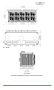
Dimensions
See Figure Above
Storage Temperature Range
-18°F to 122°F
(-28°C to 50°C)
Mounting
Supported by ground-mounted
insulators
Condensing Operating
Humidity Range
5% to 100%
Cooling
Liquid-cooling interface between
power semiconductors and fan-
equipped liquid-to-air heat
exchangers using redundant fans
and pumps all at line potential.
Sealed enclosure coolers for
controlling internal ambient
temperature.
Maximum Sustained Rain
4.0 in/hr (102 mm/hr)
Intrusion Protection
IEC 60529, Designed to
IP 55, Tested to IP X5
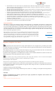
Communication
Other
Communication Architecture
EMS integration via PowerLine
Gateway
TM
located at substation
Electrical Connections
Joints that carry current
during faults and
Monitoring Mode
tested to IEC 61284.
Joints that carry current
during Injection Mode
tested to ANSI-C119.4
Communication Security
Features
The communication protocol
uses SHA-256 to ensure
cryptographic integrity of all
messages while supporting full
observability by utility firewalls.
The standard device uses an ISM
band RF protocol optimized for
fast telemetry.
Product equipped with the fiber-
optic package uses fiber-optic
communication between the
communication system and the
SmartValve devices
(8)
.
Electrical Connections
Joints that carry current
during faults and
Monitoring Mode
tested to IEC 61284.
Joints that carry current
during Injection Mode
tested to ANSI-C119.4
Sensor Accuracy
AC Line Current
(9)
± 3 %
Notes:
1. Maximum RMS AC of the output voltage for an individual device. Maximum voltage injection of a SmartValve System of n
devices in series per phase is n times the Maximum Voltage Injection of an individual device.