MXCORE 32X32 User Manual Expandable HDMI Video Switch Matrix Made in U.S.A. 1 www.SmartAVI.
TABLE OF CONTENTS WHAT'S IN THE BOX? INTRODUCTION FEATURES APPLICATIONS EDID EMULATION TECHNICAL SPECIFICATIONS HARDWARE INSTALLATION FRONT PANEL CONTROL ESTABLISHING AN RS-232 CONNECTION USING THE SmartControl SOFTWARE USING RS-232 CONTROL 2 3 3 3 3 4 5 6-7 8 9-11 12-16 USING NET-IP-PRO (TCP/IP CONTROL) 17 USING IR REMOTE CONTROL 18 LIMITED WARRANTY STATEMENT 19 WHAT’S IN THE BOX? PART NO. QTY DESCRIPTION MXC-HD32X32S 1 MXCORE-HD Expandable HDMI 32X32 Matrix Switcher.
INTRODUCTION The MXCORE 32X32 HDMI Matrix Router allows you to route up to 32 HDMI input sources to up to 32 HDMI display devices. The MXCORE 32X32 supports high resolutions of up to 1080p, along with 7.1 Digital Surround Sound Audio with no loss of picture clarity and no ghosting of images. The HDMI signal allows the transfer of both audio and video signals simultaneously. The Matrix also supports HDMI 1.4, HDCP, and DVI 1.0 protocol.
TECHNICAL SPECIFICATIONS VIDEO Video Amplifier Band3.2G width Input Video Signal Video (TMDS) 0.5~1.
HARDWARE INSTALLATION 1. Power off the computers and displays. 2. Connect the HDMI video cables from the video sources to the HDMI inputs on the rear of the MXCORE 32X32. 3. Connect the displays to the HDMI outputs on the rear of the MXCORE 32X32. 4. Optionally connect the IR Eye for IR remote control. 5. Optionally connect a computer to the RS-232 port on the MXCORE 32X32 or a NET-IP-PRO for additional remote control. 6. Power on the Video sources and displays. 7. Power on the MXCORE 32X32.
FRONT PANEL CONTROL Front Panel Buttons Figure 6-1 To lock the front panel buttons and avoid any accidental changes, press ESC + MENU + ENTER + SWITCH at the same time. The display will indicate that it is locked. Repeat the procedure to unlock the front panel. Front Panel Display Figure 6-2 Default Display: During normal operation, you will see a list of ports on the front panel display. To assign an output to an input, press SWITCH. A blinking block cursor will appear.
FRONT PANEL CONTROL (Continued) Main Menu To view the menu, press MENU. There are 6 menu options available: Figure 7-1 RS-232 Acknowledge - Sets the MXCORE 32X32 to send a confirmation that an RS-232 command has been received. Send Update - Sets the MXCORE 32X32 to send an RS-232 command back to the controller when the configuration is changed via the front panel or remote control (optional). Memory Save - Sets the MXCORE 32X32 to save the configuration when powered off.
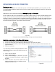
ESTABLISHING AN RS-232 CONNECTION Before you start: Controlling a Smart-AVI device via RS-232 requires an RS-232 card installed on your computer or a USB to RS-232 adapter. Below are instructions on how to create an RS-232 connection between a PC and the Smart-AVI device. Make sure to use communication settings 9600 bps, N, 8, 1, No flow control. Check the device and your PC to determine if you need a male to male or a male to female cable and how long it needs to be.
USING THE SmartControl SOFTWARE RS-232: Controlling the MXCORE32X32 has never been simpler with SmartControl software. With SmartControl, you can assign a unique name to each port on the MXCORE32X32 , as well as each display, customizing projects to meet your needs. Although all the functions of the matrix are available locally on the front panel of the MXCORE32X32 , using SmartControl allows for customization of all the matrix functions.
USING THE SmartControl SOFTWARE (continued) Main Routing Window The Main Routing Window enables you to control the router(s) connections by means of the Crosspoint panel, the button panel, or with pre-recorded routes called macros. Crosspoint Panel: This is the simplest way to route the connections. Simply click on the cross point itself. The input on the left will then be routed to the output above.
USING THE SmartControl SOFTWARE (continued) The Button Panel: Output Options: To select multiple outputs, in the row for any input or source, click the button under the desired outputs or displays. Input Options: To route an input to all the outputs at once, hold the control key down and click on an input. Macros: This section of the window is used to save and play back macros. Macros store a set sequence of routes. To record a macro: 1. Click on the Record button (last button shown).
USING RS-232 CONTROL Setting up the Terminal Application: 1. Open Hyperterminal on the PC. (or use the terminal client of your choice) 2. Use the default settings to create a connection to the device: 9600, 8, N, 1.(see settings on right). 3. Be sure that Flow Control is None. 4. The output of the device will be the same as the PC. Figure 12-1 There are two primary modes of operation for the MXCORE32x32: Command Mode and Debug Mode.
USING RS-232 CONTROL (Continued) To display the help menu for a list of commands, type “? ” or “help “ DBG>? ========================================================================== Command Line Interface Help: D Enable/Disable debug d [on]/[off] Sw Switch Port sw [output] 1-32 [input] 1-32 br Broadcast Port br [input] 1-32 om Set output mode om [output | a] [mode# (0-2) | ?] do Disable outputs do [output],[output]... eo Enable outputs eo [output],[output]...
USING RS-232 CONTROL (continued) To switch ports, type “sw [output] 1-32[input] 1-32 ”: Example: DBG>sw 2 2 This switches Output 2 to Input 2 To set the broadcast port, type “br [input] 1-32”: Example: DBG>br 2 This will send input 2 to all outputs. DBG>br \ Sets 1:1 mode. IN 1 to OUT 1 IN 2 to OUT 2 IN 3 to OUT 3 Etc. DBG>br / Sets inverse 1:1 mode. IN 1 to OUT 32 IN 2 to OUT 31 IN 3 to OUT 30 Etc.
USING RS-232 CONTROL (continued) Command Mode: allows raw commands to be sent to the MXCORE 32x32 to control its various functions without the use of a menu or prompt. This mode is intended for advanced use only.
USING RS-232 CONTROL (continued) B. Sending commands without CHECKSUM: 1. To set a video crosspoint: \\FxxMyyIzz Ex. to set video input 3 to output 12 on a router with the default frame mand: \\F00M12I03 address “0” send the com- 2. To broadcast an input to all outputs: \\FxxBzz Ex. to broadcast input 3 to all outputs, send the command: \\F00B04 3. To set RS-232 crosspoint: \\FxxRyyIzz 4.To disconnect RS-232 crosspoint: \\FxxDyyIzz *A new method is to disconnect all: //F00D 5.
USING NET-IP-PRO (TCP/IP CONTROL) The NET-IP-PRO (Sold separately) is an RS-232 control module that allows most SmartAVI switching matrixes to be controlled remotely via HTTP or TELNET. Manage the switching functions of your matrix with ease from anywhere in the world. With NET-IP-PRO you can save input/output configuration presets for easy access. TELNET access provides transparent command control of your matrix, perfect for use with automated third-party control software.
USING IR REMOTE CONTROL Switching Input / Output ports Press [IN] [1] [OUT] [4] [OK] This will send the input (source) connected to port 1 to the display connected to output port 4. Broadcasting a single input source to all output ports. Press [F1] [4] [OK] This will send input 4 to all output displays.
LIMITED WARRANTY STATEMENT A. Extent of limited warranty Smart‐AVI Technologies, Inc. warrants to the end‐user customers that the Smart‐AVI product specified above will be free from defects in materials and workmanship for the duration of 1 year, which duration begins on the date of purchase by the customer. Customer is responsible for maintaining proof of date of purchase.
NOTICE The information contained in this document is subject to change without notice. SmartAVI makes no war‐ ranty of any kind with regard to this material, including but not limited to, implied warranties of merchant‐ ability and fitness for particular purpose. SmartAVI will not be liable for errors contained herein or for inci‐ dental or consequential damages in connection with the furnishing, performance or use of this material.