u n w i r i n g o u r w o r l d airClient™ TOTAL 241 Series sB3415-01 / sB3415-02 / sB3415-03 User Guide Version 2.1 Copyright © smartBridges Pte Ltd. All Rights Reserved.
i n t e l l i g e n t w i r e l e s s p l a t fo r m CONTENTS ABOUT THIS DOCUMENT ..........................................................................................................4 Overview of User Guide......................................................................................................4 Related Publications...........................................................................................................5 Technical Support Center .......................................
i n t e l l i g e n t 5.8. 5.9. 5.10. 5.11. 5.12. w i r e l e s s p l a t fo r m FIRMWARE UPGRADE ....................................................................................................66 PRODUCT LICENSE KEY ................................................................................................68 LINK BUDGET PLANNING ................................................................................................69 SYSTEM LOG .........................................................
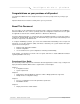
i n t e l l i g e n t w i r e l e s s p l a t fo r m Congratulations on your purchase of sB product Your airClient™ TOTAL 241 unit is designed so that you can set it up easily and be on your way to get unwired. Important: Read all user instructions carefully before you use your device. About This Document This user guide is for the networking professional who installs, configures and manages the smartBridges’ airClient™ TOTAL 241 series.
i n t e l l i g e n t w i r e l e s s p l a t fo r m Chapter 5: • The site survey tool • The system configuration tools • Backup/restore features • Firmware upgrade steps • Using the License Key feature for bandwidth upgrade on the unit. The abbreviations and acronyms used in this user guide are explained in the Appendix.
i n t e l l i g e n t w i r e l e s s p l a t fo r m 1. Introduction This user manual will guide you through initial site preparation, installation, configuration, and troubleshooting of the airClient TOTAL 241 [sB3415] unit. A web-based management tool is provided to assist the user to configure the airClient TOTAL unit for different purposes.
i n t e l l i g e n t w i r e l e s s p l a t fo r m 1.2. Checklists Deployment time, link-up time and support time can be improved by adopting proper site survey analysis, link planning, pre-installation tests, and web-GUI familiarization. The following pre-installation and postinstallation checklist attempts to give the installer the basic understanding on the points to consider for a wireless deployment.
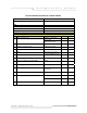
i n t e l l i g e n t w i r e l e s s No Parameters Units 18 Length of external cable connecting Radio and antenna Feet/meters 19 Fade Margin taken into account for link budgeting Ideally between 15 to 20 dB 20 Model of smartBridges airClient TOTAL equipment selected for a link.
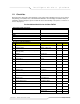
i n t e l l i g e n t w i r e l e s s p l a t fo r m Post-Installation Checklist for airClient TOTAL Organization Name/Site Name Address City State Zip Code Telephone Number General Configuration Information No Parameters Units 1 Radio operation mode 2 SSID of a Radio sB3415-01 / sB3415-02 : Router / NAT sB3415-03 : Bridge / Router / NAT Up to 32 characters 3 IP address of Ethernet Port 32-bit numeric address 4 IP address of Wireless Port 32-bit numeric address 5 RSSI dBm (At present, ‘Lev
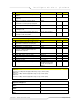
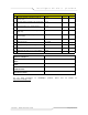
i n t e l l i g e n t Checklist No Parameters w i r e l e s s Units 1 Check the crimping of the Ethernet cable at both the ends Yes/No 2 Check the proper grounding of the antenna and equipment Yes/No 3 Ensure that there are no extreme bends or kinks in the cable Yes/No 4 Ensure Ethernet cable is not running near a sharp edge Yes/No 5 Ensure antenna is aligned to get the best RSSI and link quality Yes/No 6 Ping response ms 7 Ping success rate Percentage 8 Throughput test (Upload/Dow
i n t e l l i g e n t w i r e l e s s p l a t fo r m 2. airClient TOTAL Configuration The airClient TOTAL sB3415-01 and sB3415-02 can work in either Router or NAT mode. The airClient TOTAL sB3415-03 can work in one of the three modes: Bridge, Router or NAT. The procedures for configuring the various parameters in each mode are outlined in this chapter. Some of the details on the technical terms, acronyms and abbreviations used can be found in Appendix A. 2.1.
i n t e l l i g e n t w i r e l e s s p l a t fo r m Figure 2-2 airClient TOTAL License Agreement Page airClient™ TOTAL 3415 User Guide Page 12 of 75
i n t e l l i g e n t w i r e l e s s p l a t fo r m Figure 2-3 airClient TOTAL Summary Information Page airClient™ TOTAL 3415 User Guide Page 13 of 75
i n t e l l i g e n t w i r e l e s s p l a t fo r m The descriptions of the fields in the Summary Information page are provided in the table (Table 2-1) below: Table 2-1 Description of the field items in the ‘Summary Information’ page Field Items on Summary Info page Descriptions LAN IP Mode Set to Static IP by default System Name This is the user defined name of the unit IP Address Ethernet IP Address.
i n t e l l i g e n t w i r e l e s s p l a t fo r m 2.2. Web GUI Administrator User Name and Password Change The default administrator user name for the airClient TOTAL 3415 is administrator and administrator password is smartBridges (please note that this is case sensitive). Follow the steps below to change the administrator user name and/or password: 1. From the top navigation menu bar, click on Tools | System Admin. A System Administration interface will appear as shown below. 2.
i n t e l l i g e n t w i r e l e s s p l a t fo r m 2.3. Using the Configuration Pages The airClient TOTAL configuration system comprises several pages for configuring each parameter. A common navigation menu bar is provided at the top of each page for easy navigation as shown in the figure below (Figure 2-5). Figure 2-5 airClient TOTAL Navigation Menu Bar The Navigation menu bar contains menu items that allow the user to go to different configuration pages.
i n t e l l i g e n t Menu Item w i r e l e s s Menu Sub-items Description Wireless Statistics Displays traffic Wireless side p l a t fo r m statistics on the Shows the status of the association and the MAC of the AP associated with. Association Status DHCP DHCP List Networking IP/Port Forwarding Shows the Link Status Graph for the associated link.
i n t e l l i g e n t Menu Item Menu Sub-items w i r e l e s s p l a t fo r m Description Note: By default, Disabled. the Security mode is AES security mode is only available in 3415-03 model. System Configuration Allows user to switch the operation mode between Bridge (sB3415-03 Only), Router or NAT mode. Allows the user to Reset the unit, Restore unit to Factory defaults. SNTP Setting Allows user to set the Network Time Server and the Time Zone.
i n t e l l i g e n t Menu Item Help p l a t fo r m Menu Sub-items Description Technical Support Information on Technical Support User Guide – Online Link to online user guide Product Registration and Feedback Allows user to register product and provide feedback or suggestions. Check for Updates Checks smartBridges website for any software updates.
i n t e l l i g e n t w i r e l e s s p l a t fo r m 2.4. Device Mode Configuration The device operational mode is displayed at the top right hand corner of each page. The device mode configuration allows the user to configure the airClient TOTAL to a NAT (Network Address Translation) mode or Router mode for 3415-01 and 3415-02 models, and NAT or Router or Bridge mode for the 341503 model. These modes are explained below. NAT: This is the default operating mode.
i n t e l l i g e n t w i r e l e s s p l a t fo r m 2.5. Changing from NAT to Router Mode The default configuration of the airClient TOTAL is in the NAT mode. Follow the steps below to change the airClient TOTAL from the default NAT mode to Router mode: 1. From the navigation menu bar, click on Tools | System Configuration. The System Configuration page will appear as shown below. 2. Under the Current Operational Mode, choose the operation mode Router. 3.
i n t e l l i g e n t w i r e l e s s p l a t fo r m 2.6. Changing from Router to NAT Mode Follow the steps below to change the airClient TOTAL from Router Mode to NAT Mode: 1. From the navigation menu bar, click on Tools | System Configuration. The System Configuration screen will appear as shown below. 2. Under the Current Operational Mode, choose the operation mode NAT. 3. Click on Save to reboot the unit and convert to NAT mode. 4.
i n t e l l i g e n t w i r e l e s s p l a t fo r m 3. Click on Save to convert the unit to Bridge mode. 4. The Bridge Mode on sB3415 can be configured to operate in WDS and non-WDS modes. For all the different modes configuration in Bridge Mode, refer to Section 2.9. Figure 2-9 Changing Router/NAT Mode to Bridge Mode (sB3415-03 only) 2.8. Changing from Bridge to Router/NAT Mode (sB3415-03 Only) This section is only valid for the sB3415-03 model.
i n t e l l i g e n t w i r e l e s s p l a t fo r m Figure 2-10 Changing Bridge Mode to Router (or NAT) Mode (sB3415-03 Only) airClient™ TOTAL 3415 User Guide Page 24 of 75
i n t e l l i g e n t w i r e l e s s p l a t fo r m 2.9. airClient TOTAL Bridge Configuration (sB3415-03 only) This section is only valid for the sB3415-03 model. The sB3415-03 can be configured in both WDS and non-WDS modes, while in Bridge Mode. In WDS mode, 3415 functions as a transparent bridge. In non-WDS client bridge mode, 3415 can be configured for both non-transparent and transparent bridging. This section covers the configuration of the sB3415-03 in all possible bridge modes. 2.9.1.
i n t e l l i g e n t w i r e l e s s p l a t fo r m Figure 2-11 airClient TOTAL WDS Bridge Mode Configuration (sB3415-03 Only) LAN Settings This section outlines the procedures for changing the IP settings for bridge mode – 1. From the navigation menu bar, click on Home | LAN Settings to change Ethernet/wired side parameters. The LAN Settings screen will appear as shown below in Fig 2-12. 2. Enter the System Name of the unit, if needed. 3.
i n t e l l i g e n t w i r e l e s s p l a t fo r m Figure 2-12 airClient TOTAL Bridge LAN Settings (sB3415-03 Only) Radio Settings Follow the steps below to configure the Radio parameters in the airClient TOTAL WDS Bridge Mode : 1. From the navigation menu bar, click on Radio | Wireless Settings to set the radio parameters. The Wireless Settings screen will be displayed as shown in Fig 2-13. 2. Set the SSID, and the wireless mode to either 802.11 b/g. 3.
i n t e l l i g e n t w i r e l e s s p l a t fo r m Figure 2-13 airClient TOTAL WDS Bridge Radio Settings (sB3415-03 Only) Figure 2-14a airClient TOTAL Summary Information Page Figure 2-14b airClient TOTAL Wireless Association Status airClient™ TOTAL 3415 User Guide Page 28 of 75
i n t e l l i g e n t w i r e l e s s p l a t fo r m 2.9.2. Client Bridge Mode (Non-WDS) The sB3415-03 can also be configured to operate in the non-WDS Bridge Mode. It is said to be operating in the Client Bridge mode in this configuration. The airClient TOTAL can associate with any Access Point in this bridge mode. The Client Bridge mode can be configured for both Non-Transparent and Transparent bridging. In Non-Transparent bridging, you can connect more than 1 device behind the airClient TOTAL unit.
i n t e l l i g e n t w i r e l e s s p l a t fo r m Figure 2-15 airClient TOTAL Non-Transparent bridging Configuration (sB3415-03 Only) LAN Settings This section outlines the procedures for changing the IP settings for bridge mode. These settings are the same in all possible bridge modes – 1. From the navigation menu bar, click on Home | LAN Settings to change IP address and mask of the unit in bridge mode. The LAN Settings screen will appear as shown below in Fig 2-16. 2.
i n t e l l i g e n t w i r e l e s s p l a t fo r m Figure 2-16 airClient TOTAL Bridge LAN Settings (sB3415-03 Only) Radio Settings Follow the steps below to configure the Radio parameters in the airClient TOTAL Bridge Mode, for NonTransparent bridging : 1. From the navigation menu bar, click on Radio | Wireless Settings to set the radio parameters. The Wireless Settings screen will be displayed as shown in Fig 2-17. 2. Set the SSID, and the wireless mode to either 802.11b/g. 3.
i n t e l l i g e n t w i r e l e s s p l a t fo r m Figure 2-17 airClient TOTAL Bridge Radio Settings – Non-Transparent bridging (sB3415-03 Only) Note : In non-transparent bridging configuration, when airClient TOTAL is associated, the MAC addresses seen on the AP Association table, will be the MAC address of the sB3415-03 device, and not of the devices behind the sB3415-03 unit.
i n t e l l i g e n t w i r e l e s s p l a t fo r m Figure 2-18 airClient TOTAL Transparent Bridging Configuration (sB3415-03 Only) LAN Settings This section outlines the procedures for changing the IP settings for bridge mode. These settings are the same in all possible bridge modes – 1. From the navigation menu bar, click on Home | LAN Settings to change IP address and mask of the unit in bridge mode. The LAN Settings screen will appear as shown below in Fig 2-19. 2.
i n t e l l i g e n t w i r e l e s s p l a t fo r m Figure 2-19 airClient TOTAL Bridge LAN Settings (sB3415-03 Only) Radio Settings Follow the steps below to configure the Radio parameters in the airClient TOTAL Bridge Mode, for Transparent bridging : 1. From the navigation menu bar, click on Radio | Wireless Settings to set the radio parameters. The Wireless Settings screen will be displayed as shown in Fig 2-20. 2. Set the SSID, and the wireless mode to either 802.11b/g. 3.
i n t e l l i g e n t w i r e l e s s p l a t fo r m Figure 2-20 airClient TOTAL Bridge Radio Settings –Transparent bridging (sB3415-03 Only) Note : In Transparent bridging configuration, when airClient TOTAL is associated, the MAC address seen on the AP Association table, will be the MAC address of the device connected behind the sB3415-03 device.
i n t e l l i g e n t w i r e l e s s p l a t fo r m 2.10. airClient TOTAL Router / NAT Configuration This section covers the procedures for configuring various parameters in the Router and NAT modes. 2.10.1. LAN Settings The LAN and the WLAN settings are maintained in two different subnets. Follow the steps below to re-configure the airClient TOTAL Router/NAT Ethernet parameters: 1. From the navigation menu bar, click on Home | LAN Settings to change Ethernet/wired side parameters.
i n t e l l i g e n t 2.10.2. w i r e l e s s p l a t fo r m WLAN Settings The wireless parameters need to be configured to allow the airClient TOTAL unit to associate with an airPoint™ Nexus device or any other third party wireless access point. Follow the steps below to configure the airClient TOTAL Router/NAT Mode Wireless IP Settings parameters: 1. From the navigation menu bar, click on the Home | WLAN Settings to set the wireless parameters for the unit.
i n t e l l i g e n t w i r e l e s s p l a t fo r m Figure 2.23 airClient TOTAL Router/NAT WLAN Settings – Dynamic WLAN Connection For the airClient TOTAL device to associate with an access point, the user also needs to configure the access point’s SSID, security (if used), and select External/Internal antenna options.
i n t e l l i g e n t w i r e l e s s p l a t fo r m Follow the steps below to configure the airClient TOTAL Router/NAT Mode wireless association parameters: 1. From the navigation menu bar, click on Radio | Wireless Settings to set the SSID and wireless mode (802.11 b/g). The Wireless Settings screen will be displayed as shown in Fig 2-24. 2. Set the SSID, and the wireless mode to either 802.11 b/g. 3. The Channel selection is disabled in the Router/NAT mode.
i n t e l l i g e n t w i r e l e s s p l a t fo r m Figure 2-24 airClient TOTAL Router Wireless Settings Figure 2-25a airClient TOTAL Summary Information page airClient™ TOTAL 3415 User Guide Page 40 of 75
i n t e l l i g e n t w i r e l e s s p l a t fo r m Figure 2-25b airClient TOTAL Wireless Association Status Figure 2-25c airClient TOTAL Association Status Graph Noise Floor is the measurement of the signal created from the sum of all the noise sources and unwanted signals within a measurement system. Note: If the Status Graph window does not appear, click on the Java link to download the JRE.
i n t e l l i g e n t 2.10.3. w i r e l e s s p l a t fo r m DHCP Configurations The airClient TOTAL unit can be used as a DHCP server. DHCP (Dynamic Host Configuration Protocol) allows a host to be automatically assigned a new IP address out of a pool of preconfigured IP addresses for the network. This feature will only work when the unit is in Router or NAT operating mode. Follow the steps below to configure the airClient TOTAL unit as a DHCP server: 1.
i n t e l l i g e n t w i r e l e s s p l a t fo r m Figure 2-26 airClient TOTAL DHCP Server Configurations Figure 2-27 airClient TOTAL DHCP List Follow the steps below to disable the airClient TOTAL Router/NAT DHCP server: 1. From the Navigation menu bar, click on Networking | DHCP Server to access the DHCP configuration page. 2. Select the DHCP and DHCP Relay button to disable the DHCP server configuration. 3. Click on Save to save the settings. The settings will be applied after the Reboot.
i n t e l l i g e n t w i r e l e s s p l a t fo r m Figure 2-28 Disable DHCP and DHCP Relay 2.10.4. DHCP Relay Configuration If the user has a DHCP Server, the airClient TOTAL Router can be configured as a DHCP Relay agent of the DHCP Server for IP address assignment. Follow the steps below to configure the airClient TOTAL unit as a DHCP Relay Agent: 1. From the Navigation menu bar, click on Networking | DHCP Server to access the DHCP configuration page. 2.
i n t e l l i g e n t 2.10.5. w i r e l e s s p l a t fo r m IP/Port Forwarding IP/Port forwarding (also referred to as Virtual Server in this document) allows the user to define the port mapping between the local area network and the public network. This feature is only available when the device is configured in the NAT mode. Follow the steps below to map a local port to the global port (accessible through the wireless interface): 1.
i n t e l l i g e n t w i r e l e s s p l a t fo r m Figure 2-31 IP/Port Forwarding Table Entries on Summary Page Follow the steps below to edit or delete a port forwarding entry in the airClient TOTAL operating in NAT Mode. 1. Click on Networking | IP/Port Forwarding from the menu bar to access the Port Forwarding Table page. 2. In case you want to edit an existing entry, click on the Edit corresponding to the row. The entries will show up in the fields.
i n t e l l i g e n t w i r e l e s s p l a t fo r m Adding and deleting static routes is allowed in the Router Mode of the airClient TOTAL. Follow the steps below to add a static route entry in the airClient TOTAL operating in the Router Mode. 1. Click on Networking | Routing Table from the menu bar to access the routing table page. 2. Enter the Destination IP, IP Mask, Gateway for the new route. Select Add to add a new route as shown in Fig 2-33. 3.
i n t e l l i g e n t w i r e l e s s p l a t fo r m Follow the steps below to edit or delete a static route entry in the airClient TOTAL operating in the Router Mode. 1. Click on Networking | Routing Table from the menu bar to access the view routing table page. 2. From the Routing table on this page, select the route you wish to delete, and click Delete, as shown in Fig 2-35. 3. In case you want to edit the existing entry, click on the Edit corresponding to the row.
i n t e l l i g e n t w i r e l e s s p l a t fo r m 2.11. Security This section allows you to configure wireless encryption to prevent unauthorized parties from accessing the network. The security options on the airClient TOTAL are as follows: 1. Open System 2. Shared Key 3. WPA –PSK Note: By default, security is Disabled. 2.11.1. Open System / Shared Key Open System/Shared Key authentication is used for security between the airClient TOTAL and the airPoint Nexus (or any other access point).
i n t e l l i g e n t w i r e l e s s p l a t fo r m Figure 2-36 airClient TOTAL Security - Open System/Shared Key Configuration Table 2-3 Security Settings for Open System/Shared Key Page Items Descriptions Choose between open system and shared key authentication modes Authentication Type Open System: Open System is null authentication. With WEP enabled and valid WEP key on both ends, it provides data encryption. Shared Key: Strict authentication for both authentication and data encryption.
i n t e l l i g e n t w i r e l e s s p l a t fo r m 1. Click on Radio | Security from the main menu. A screen as shown in the figure below will appear for the WPA-PSK settings. 2. Select the Authentication Type as WPA-PSK from the drop down menu. 3. Enter the Key Entry Method as ASCII or HEX. 4. Enter the WPA-Shared Key in the Passphrase field. 5. Select the Cipher as TKIP or AES. (Note: AES cipher is only available in 3415-03 model). 6. Click on Save and click on Tools | Reboot to reboot the unit.
i n t e l l i g e n t w i r e l e s s p l a t fo r m 3. Wireless Settings and Bandwidth Controller 3.1. Wireless Settings The Wireless Settings can be accessed from the Radio | Wireless Settings in the navigation menu bar. Figure 3-1 airClient TOTAL Wireless Settings The following table summarizes the information for the wireless settings. Table 3-1 Wireless Settings Page Items SSID SSID Suppressed Channel Remote AP MAC Address Descriptions The network name for the wireless network.
i n t e l l i g e n t Page Items Wireless Mode w i r e l e s s p l a t fo r m Descriptions 03 only) For Router/NAT modes or Client Bridge Mode (3415-03 only), this MAC address needs to be set to 00:00:00:00:00:00 This is the radio operating mode of the client. This can be set to the wireless 802.11b or 802.11g. Antenna Selection This sets the Antenna to Internal or External.
i n t e l l i g e n t w i r e l e s s p l a t fo r m 3.2. Bandwidth Control Using the Bandwidth Controller, the user can limit the wireless link bandwidth speed. The maximum allowable bandwidth is up to 512Kbps in sB3415-01, 1 Mbps in 3415-02 and 3 Mbps in 3415-03. This is subject to the available upstream bandwidth, signal level and distance.
i n t e l l i g e n t w i r e l e s s p l a t fo r m Figure 3-3 airClient TOTAL Bandwidth Control (sB3415-03) airClient™ TOTAL 3415 User Guide Page 55 of 75
i n t e l l i g e n t w i r e l e s s p l a t fo r m 3.2.2. Ethernet Bandwidth Control (sB3415-03 only) Note: This section is only applicable for sB3415-03. sB3415-03 allows you to limit the amount of bandwidth for each device connected on the Ethernet side, to allow for proper sharing of the bandwidth. The bandwidth on the Ethernet side can be limited based on the IP address of the device, or its MAC address.
i n t e l l i g e n t w i r e l e s s p l a t fo r m Follow the steps below to control the Bandwidth parameters on the Ethernet side, based on MAC address: 1. From the navigation menu bar, click on Networking | Bandwidth Control. 2. In the Ethernet Bandwidth Control settings. click on the Enable Bandwidth BWC button to enable the Ethernet bandwidth controlling feature. 3. To control the Ethernet BWC, based on the MAC address, enter a valid MAC Address of the PC in the place shown in Fig 3.
i n t e l l i g e n t w i r e l e s s p l a t fo r m 1. Click on Networking | Bandwidth Control from the menu bar to access the Bandwidth Control page, as shown below for MAC based Ethernet BWC in Fig 3-6. 2. In the Ethernet Bandwidth Control Settings, click on the Edit corresponding to the row you wish to edit. The entries will show up in the fields above. Edit the entries and click the Update button to update the table. 3.
i n t e l l i g e n t w i r e l e s s p l a t fo r m 4. Traffic Statistics Wireless Statistics can be displayed by clicking on Networking | Wireless Statistics from the navigation menu. The following figure shows the statistics page. Figure 4-1 airClient TOTAL Wireless Statistics The following table summarizes the information for the wireless traffic settings.
i n t e l l i g e n t w i r e l e s s p l a t fo r m 5. Tools In this section, you will find relevant information for changing the operating mode of the device, saving the configuration, restoring to factory defaults and upgrading the firmware. 5.1. System Configuration The System Configuration page allows the user to change the operating mode of the unit. Click on Tools | System Configuration from the navigation menu bar, to access the System Configuration page.
i n t e l l i g e n t w i r e l e s s p l a t fo r m The following table summarizes the information for the System Configuration page. Table 5-1 System Configuration Page Items Page Item System Name SNMP Configuration Reset SNTP Server Firmware Version Local MAC Address Reset to Factory Defaults Ethernet MTU Size System Log Current Operational Mode Descriptions. Name of the airClient TOTAL. This field links to the SNMP Configuration page settings. This button Resets the airClient TOTAL unit.
i n t e l l i g e n t w i r e l e s s p l a t fo r m 5.3. Site Survey From the navigation menu bar, click on Tools | Site Survey to access the Site Survey page. A screen, similar to the one below, would show all the standards-based wireless devices operating in the area. Figure 5-3 airClient TOTAL Site Survey The following table summarizes the information for the Site Survey items. Table 5-2 Site Survey Page Items Page Item Descriptions.
i n t e l l i g e n t 5.4. w i r e l e s s p l a t fo r m System Admin This menu option allows the user to change the User Name and/or password to access the unit. Refer to chapter 2.2 to change the user name and/or administrator password. The default user name is administrator and the default password is smartBridges (case sensitive). 5.5. System User The airClient TOTAL unit allows the user to create Read Only users, to only allow the users to only view the configurations of the unit.
i n t e l l i g e n t 5.6. w i r e l e s s p l a t fo r m SNMP Configuration The user can enable or disable the SNMP configuration using this tool. Follow the steps below to change the SNMP settings: 1. Click on Tools | SNMP Configuration to access the SNMP Configuration page, as shown below in Fig 5-5. 2. Enable or Disable SNMP by using the checkbox. 3. Set the Read Community String to smartBridges. 4. Set the System Contact/Location on the page, if required. 5.
i n t e l l i g e n t 5.7. w i r e l e s s p l a t fo r m Backup/Restore Settings The Backup/Restore page backs up good configuration settings of the system. This can be used to restore the unit in case of any undesired circumstances. Follow the steps below to change the Backup/Restore settings: 1. From the navigation menu bar, click on Tools | Backup/Restore to save or restore the settings on the unit. A page will appear as shown below. 2.
i n t e l l i g e n t 5.8. w i r e l e s s p l a t fo r m Firmware Upgrade The airClient TOTAL unit firmware can be upgraded from the web management interface. The latest firmware for airClient TOTAL is available for download from the smartBridges support website at http://www.smartbridges.com/support/aCT241.asp. Follow the steps below to upgrade the airClient TOTAL firmware: 1. Download the latest (or a particular release version) of the airClient TOTAL firmware from the web URL - http://www.
i n t e l l i g e n t w i r e l e s s p l a t fo r m Figure 5-8 airClient TOTAL Firmware Upgrade Figure 5-9 airClient TOTAL Successful Firmware Upgrade message airClient™ TOTAL 3415 User Guide Page 67 of 75
i n t e l l i g e n t 5.9. w i r e l e s s p l a t fo r m Product License Key This feature is used to enhance/upgrade the default bandwidth on the airClient TOTAL units, and to convert the models between sB3415-01, sB3415-02 and sB3415-03. By default, the 3415-01 allows a maximum bandwidth of 512 kbps, 3415-02 allows a bandwidth of 1 Mbps, and 3415-03 allows a bandwidth of 3 Mbps.
i n t e l l i g e n t 5.10. w i r e l e s s p l a t fo r m Link Budget Planning Link Budget Planning is a very useful tool for link budget estimation. A GPS Calculator is provided in the Link Budget Planning Calculator page to calculate the distance between an airClient TOTAL unit and an access point. To calculate the distance between the two, follow the steps below: 1. From the top navigation menu bar, click on Tools | Link Budget Planning.
i n t e l l i g e n t w i r e l e s s p l a t fo r m 5. Click the Compute Link Budget button to calculate the link budget information. 6. The link budget information will be displayed as shown below in Fig 5-12. The link budget information includes the EIRP, Free Space Loss and Theoretical RSSI. The Receive Sensitivity, Maximum Transmit Power, System Gain and Available Fade Margin at various Link Speeds are also computed and displayed in a table.
i n t e l l i g e n t 5.11. w i r e l e s s p l a t fo r m System Log sB3415 allows the System logs to be created locally or remotely on the PC connected to the unit. Local logging is persistent across resets of the 3415-01/02/03 units. To configure the System Log on the 3415 device, follow the steps below: 1. From the top navigation menu bar, click on Tools | System Log. The System Log web page will appear as shown below in Fig 5-13. 2. By default, the Syslog level is set to Information.
i n t e l l i g e n t w i r e l e s s p l a t fo r m To refresh or clear the Syslog entries logged locally on the device, follow the steps below: 1. Select Tools | System Log from the Navigation menu bar. The System Log web page will appear as shown above in Fig 5-13. 2. At the bottom of this page, there are two buttons, Refresh and Clear. 3. Click on Refresh button to refresh the logs shown on the web page. 4. Click on Clear button to clear all the logs stored locally on the unit.
i n t e l l i g e n t 5.12. w i r e l e s s p l a t fo r m Reboot The device would need to be rebooted in case any changes are to be made to the system, or a new firmware is downloaded. Click on Tools | Reboot to reboot the unit. A figure showing the countdown to 0 will appear as shown below during the Reboot process.
i n t e l l i g e n t w i r e l e s s p l a t fo r m Appendix A – Some useful terms and definitions MAC RSSI SSID DHCP ACL SNMP SNTP STP TCP IP WDS Acronyms and Abbreviations Media Access Control Receive Signal Sensitivity Indication Service Set Identifier Dynamic Host Configuration Protocol Access Control List Simple Network Management Protocol Simple Network Time Protocol Spanning Tree Protocol Transmission Control Protocol Internet Protocol Wireless Distribution System SSID Each ESS has a Service S
i n t e l l i g e n t w i r e l e s s p l a t fo r m COFDM COFDM involves modulating the data onto a large number of carriers using the OFDM technique.