The SmarTek Video Detection System (SVS-1) User Guide-Part B Using SVS Setup and Monitor Version 3 31 May 2011
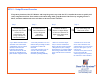
SVS-1 – Setup Process Overview The primary function of the SVS Monitor and Setup Program is to provide the SVS-1 installer the means to quickly and easily setup Detection Line Zones within each camera image field, group Detection Line Zones by assigning them to a Phase, and then combine and route each Phase to the intersection controller.
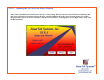
SVS-1 – Opening the SVS Set Line Zones Window After camera installation and connection to the SVS-1 Video Image Detection System, run SVS Monitor and Setup and choose the appropriate connection between the SVS-1 and the Windows PC being used. If setting up the SVS-1 shelf mount processor (up to six camera channels), click the network button. If setting up the SVS-1 single camera card, click the RS-232 button.
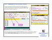
SVS-1 – Opening the SVS Set Line Zones Window If a network connection is selected, set the SVS-1 IP address and Port number in the SVS Network Connection screen. Click the Connect button and note the connection status to make sure a connection was made. Keep the Network Connection Window open. 1 2 and 3 1) Click in the upper/lower part of the Current SVS ID field to select the SVS ID (Camera Channel). 2) Click the SVS/Get SVS Parameters menu item. The yellow parameter warning label goes away.
Setting up the SVS-1 using SVS Setup and Monitor Version 3 (PC Required) After clicking the SVS/Get Image for Zone Setup menu item to open the Zone Setup window, the following steps outline the setup procedure: 1) The Main Setup display has several options. For initial SVS-1 setup, first click the Draw LZs button to proceed to the Draw Line Zones display to draw each detection line zone (create multiple line zones for each lane) and then assign or group line zones to an intersection phase.
Main Setup Display When setting up an SVS-1 camera channel for detection, the user should proceed by first Drawing Line Zones, then Setting LZ Parameters, then Setting Detector Output, and finally Setting the descriptive text for the Output Video Display. Click Draw Line Zones button.
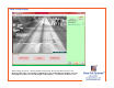
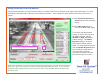
Draw Line Zones Set Line Zone Position, Size and Phase Group: 2 1 3 4 6 Phase assignment Codes: 1) Click the LZ= button to select the line zone to draw. If the previous line zone has been assigned a phase, clicking the Use Previous Values button will assign that phase to the currently selected line zone. 2) Draw the Line Zone position by left clicking (hold down left button) at the down road end of the Line Zone and drawing the Line Zone to the up road end (at this end, release the left button).
Draw Line Zones SVS-1 detection is directional, hence, be sure the direction arrow on each line zone is pointed in the correct direction of travel. The selected line zone is shown in green, all others are shown in red (show in output video) or gray (not show in output video). Phase 6R Phase 6T Phase 1L After drawing all line zones and grouping by phase, click the Main Setup button to return to the Main Setup Display.
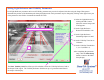
Setting Detection Zone Parameters The sensitivity parameters for each Line Zone and it’s associated Circle Zone are displayed to the right of the camera image. For most installations, default parameter values provide excellent performance.
Setting Light Reference and Visibility Parameters Each Light Reference parameter and/or each Visibility parameter may need to be adjusted after observing the Image Histogram to determine the position of the dominant peak during daylight periods. Each parameter may be changed by clicking in the upper/lower part of the parameter value field to increment/decrement the value. 1) Select the Light Reference by clicking the LZ = button below the camera image until L Ref appears.
Setting Output - Example Scenario Summary From the Main Setup display, proceed to the Set Output display by clicking the Set Output button. This display is used to specify the detector interface type , combine phases into vehicle presence relays, and then route them to output detector channels. After setting up the output relay signals, return to the Main Setup display by clicking the Main button.
Setting Output Example Scenario Summary (Continued) 4) BIU #1 Card file Detector/Controller Interface with 4 Relays per SVS-1 card, Slot 4 used, and 3 Phases (Line Zone Groups) Phase 3L, Detection Delay=0 sec, Detection Extension=0, Route to Detector Channel D5 Phase 8T, Detection Delay=0 sec, Detection Extension=0, Route to Detector Channel D6 Phase 8R, Detection Delay=2 sec, Detection Extension=2, Route to Detector Channel D6 5) BIU #1 Card file Detector/Controller Interface with 2 Relays per SVS-1 card
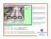
Scenario 1 Set Output Relays Type-170 Detector/Controller Interface with 4 Relays per SVS-1 card and 3 Phases (Line Zone Groups) Phase 1L, Detection Delay=0 sec, Detection Extension=0, Route to Card Edge F Phase 6T, Detection Delay=0 sec, Detection Extension=0, Route to Card Edge W Phase 6R, Detection Delay=2 sec, Detection Extension=0, Route to Card Edge W 7 4 1 6 2 3 5 Specifies Routing to Onboard Output Relay Connector (1, 2, ..
Scenario 1 Set Output Relays Type-170 Detector/Controller Interface with 4 Relays per SVS-1 card and 3 Phases (Line Zone Groups) Phase 1L, Detection Delay=0 sec, Detection Extension=0, Route to Card Edge F Phase 6T, Detection Delay=0 sec, Detection Extension=0, Route to Card Edge W Phase 6R, Detection Delay=2 sec, Detection Extension=0, Route to Card Edge W 7 4 6 1 2 3 5 Specifies Routing to Onboard Output Relay Connector (1, 2, ..
Scenario 1 Set Output Relays Type-170 Detector/Controller Interface with 4 Relays per SVS-1 card and 3 Phases (Line Zone Groups) Phase 1L, Detection Delay=0 sec, Detection Extension=0, Route to Card Edge F Phase 6T, Detection Delay=0 sec, Detection Extension=0, Route to Card Edge W Phase 6R, Detection Delay=2 sec, Detection Extension=0, Route to Card Edge W 7 4 6 1 2 3 5 Specifies Routing to Onboard Output Relay Connector (1, 2, ..
Scenario 2 Set Output Relays Type-170 Detector/Controller Interface with 2 Relays per SVS-1 card and 3 Phases (Line Zone Groups) Phase 1L, Detection Delay=0 sec, Detection Extension=0, Route to Card Edge F Phase 6T, Detection Delay=0 sec, Detection Extension=0, Route to Card Edge W Phase 6R, Detection Delay=2 sec, Detection Extension=0, Route to Card Edge W Select Detector Interface and Route Relays: 1) Click the Detector Interface button to select the type of detector/controller interface to be used ( Type
Scenario 2 Set Output Relays Type-170 Detector/Controller Interface with 2 Relays per SVS-1 card and 3 Phases (Line Zone Groups) Phase 1L, Detection Delay=0 sec, Detection Extension=0, Route to Card Edge F Phase 6T, Detection Delay=0 sec, Detection Extension=0, Route to Card Edge W Phase 6R, Detection Delay=2 sec, Detection Extension=0, Route to Card Edge W Select Detector Interface and Route Relays: 1) Click the Detector Interface button to select the type of detector/controller interface to be used ( Type
Scenario 2 Set Output Relays Type-170 Detector/Controller Interface with 2 Relays per SVS-1 card and 3 Phases (Line Zone Groups) Phase 1L, Detection Delay=0 sec, Detection Extension=0, Route to Card Edge F Phase 6T, Detection Delay=0 sec, Detection Extension=0, Route to Card Edge W Phase 6R, Detection Delay=2 sec, Detection Extension=0, Route to Card Edge W 7 4 6 1 2 3 5 Specifies Routing to Onboard Output Relay Connector (1, 2, ..
Scenario 3 Set Output Relays BIU #1 Card file Detector/Controller Interface with 4 Relays per SVS-1 card, Slot 2 used, and 3 Phases (Line Zone Groups) Phase 3L, Detection Delay=0 sec, Detection Extension=0, Route to Detector Channel D1 Phase 8T, Detection Delay=0 sec, Detection Extension=0, Route to Detector Channel D2 Phase 8R, Detection Delay=2 sec, Detection Extension=2, Route to Detector Channel D2 3 7 4 1 2 5 6 Specifies Routing to Onboard Output Relay Connector (1, 2, ..
Scenario 3 Set Output Relays BIU #1 Card file Detector/Controller Interface with 4 Relays per SVS-1 card, Slot 2 used, and 3 Phases (Line Zone Groups) Phase 3L, Detection Delay=0 sec, Detection Extension=0, Route to Detector Channel D1 Phase 8T, Detection Delay=0 sec, Detection Extension=0, Route to Detector Channel D2 Phase 8R, Detection Delay=2 sec, Detection Extension=2, Route to Detector Channel D2 3 7 4 6 1 2 5 Specifies Routing to Onboard Output Relay Connector (1, 2, ..
Scenario 3 Set Output Relays BIU #1 Card file Detector/Controller Interface with 4 Relays per SVS-1 card, Slot 2 used, and 3 Phases (Line Zone Groups) Phase 3L, Detection Delay=0 sec, Detection Extension=0, Route to Detector Channel D1 Phase 8T, Detection Delay=0 sec, Detection Extension=0, Route to Detector Channel D2 Phase 8R, Detection Delay=2 sec, Detection Extension=2, Route to Detector Channel D2 3 7 4 6 1 2 5 Specifies Routing to Onboard Output Relay Connector (1, 2, ..
Scenario 4 Set Output Relays BIU #1 Card file Detector/Controller Interface with 4 Relays per SVS-1 card, Slot 4 used, and 3 Phases (Line Zone Groups) Phase 3L, Detection Delay=0 sec, Detection Extension=0, Route to Detector Channel D5 Phase 8T, Detection Delay=0 sec, Detection Extension=0, Route to Detector Channel D6 Phase 8R, Detection Delay=2 sec, Detection Extension=2, Route to Detector Channel D6 3 7 4 6 1 2 5 Specifies Routing to Onboard Output Relay Connector (1, 2, ..
Scenario 4 Set Output Relays BIU #1 Card file Detector/Controller Interface with 4 Relays per SVS-1 card, Slot 4 used, and 3 Phases (Line Zone Groups) Phase 3L, Detection Delay=0 sec, Detection Extension=0, Route to Detector Channel D5 Phase 8T, Detection Delay=0 sec, Detection Extension=0, Route to Detector Channel D6 Phase 8R, Detection Delay=2 sec, Detection Extension=2, Route to Detector Channel D6 3 7 4 6 2 1 5 Specifies Routing to Onboard Output Relay Connector (1, 2, ..
Scenario 4 Set Output Relays BIU #1 Card file Detector/Controller Interface with 4 Relays per SVS-1 card, Slot 4 used, and 3 Phases (Line Zone Groups) Phase 3L, Detection Delay=0 sec, Detection Extension=0, Route to Detector Channel D5 Phase 8T, Detection Delay=0 sec, Detection Extension=0, Route to Detector Channel D6 Phase 8R, Detection Delay=2 sec, Detection Extension=2, Route to Detector Channel D6 3 7 4 1 6 2 5 Specifies Routing to Onboard Output Relay Connector (1, 2, ..
Scenario 5 Set Output Relays BIU #1 Card file Detector/Controller Interface with 2 Relays per SVS-1 card, Slot 2 used, and 3 Phases (Line Zone Groups) Phase 3L, Detection Delay=0 sec, Detection Extension=0, Route to Detector Channel D1 Phase 8T, Detection Delay=0 sec, Detection Extension=0, Route to Detector Channel D2 Phase 8R, Detection Delay=2 sec, Detection Extension=2, Route to Detector Channel D2 Select Detector Interface and Route Relays: 1) Click the Detector Interface button to select the type of d
Scenario 5 Set Output Relays BIU #1 Card file Detector/Controller Interface with 2 Relays per SVS-1 card, Slot 2 used, and 3 Phases (Line Zone Groups) Phase 3L, Detection Delay=0 sec, Detection Extension=0, Route to Detector Channel D1 Phase 8T, Detection Delay=0 sec, Detection Extension=0, Route to Detector Channel D2 Phase 8R, Detection Delay=2 sec, Detection Extension=2, Route to Detector Channel D2 3 7 4 1 6 2 5 Specifies Routing to Onboard Output Relay Connector (1, 2, ..
Scenario 5 Set Output Relays BIU #1 Card file Detector/Controller Interface with 2 Relays per SVS-1 card, Slot 2 used, and 3 Phases (Line Zone Groups) Phase 3L, Detection Delay=0 sec, Detection Extension=0, Route to Detector Channel D1 Phase 8T, Detection Delay=0 sec, Detection Extension=0, Route to Detector Channel D2 Phase 8R, Detection Delay=2 sec, Detection Extension=2, Route to Detector Channel D2 3 7 4 1 6 2 5 Specifies Routing to Onboard Output Relay Connector (1, 2, ..
Scenario 6 Set Output Relays BIU #1 SDLC Detector/Controller Interface with 3 Phases (Line Zone Groups) Phase 5L, Detection Delay=0 sec, Detection Extension=0, Route to Detector Channel D7 Phase 2T, Detection Delay=0 sec, Detection Extension=0, Route to Detector Channel D8 Phase 2R, Detection Delay=2 sec, Detection Extension=0, Route to Detector Channel D8 6 3 1 5 2 4 Specifies Routing to Onboard Output Relay Connector (1, 2, ..
Scenario 6 Set Output Relays BIU #1 SDLC Detector/Controller Interface with 3 Phases (Line Zone Groups) Phase 5L, Detection Delay=0 sec, Detection Extension=0, Route to Detector Channel D7 Phase 2T, Detection Delay=0 sec, Detection Extension=0, Route to Detector Channel D8 Phase 2R, Detection Delay=2 sec, Detection Extension=0, Route to Detector Channel D8 6 3 1 5 2 4 Specifies Routing to Onboard Output Relay Connector (1, 2, ..
Scenario 6 Set Output Relays BIU #1 SDLC Detector/Controller Interface with 3 Phases (Line Zone Groups) Phase 5L, Detection Delay=0 sec, Detection Extension=0, Route to Detector Channel D7 Phase 2T, Detection Delay=0 sec, Detection Extension=0, Route to Detector Channel D8 Phase 2R, Detection Delay=2 sec, Detection Extension=0, Route to Detector Channel D8 6 3 5 1 2 4 Specifies Routing to Onboard Output Relay Connector (1, 2, ..
Set Output Video Text Display This display is used to enter descriptive text which may be set to show on the output video image. Enter descriptive text in the text box below the image. To change the text position, click on the text label in the image area (do not hold the button down) and move the mouse pointer to the new location and click again.
Closing Setup Windows and Saving Setup Parameters Next, click the OK button on the Detection Zone Setup window to capture the settings and close the window. In addition to the Set Output display previously described, the Detection Line Zone Mapping display may also be used to combine Detection Line Zones and assign them to Phases and then route the Phases to output detector channels.
Assigning Line Zones to a Phase and Routing to the Output Detector Channels This display may also be used to combine Detection Line Zones (columns) and assign them to a Phase (rows) on the left half of the display. The right half of the display is then used to combine Phases (via ANDing or ORing) and route them (rows) to Detection Channels (columns- D01, D02, etc.).
Combining Line Zones and Assigning Them to a Phase This display is used to combine and assign multiple Detection Line Zones to each Phase . The Detection Line Zone to Phase Mapping Matrix has the Phase label on the vertical axis and the Detection Line Zone # on the horizontal axis. Each checked box specifies that a Detection Line Zone (column) will contribute to a Phase (row).
Routing/Mapping Each Phase to an On Board Connector Relay Position The three columns at the center of the window are used to set the Detection Extension (seconds) and the Detection Delay (seconds) for each Phase, and the mapping or routing of each Phase to an output relay position of the Green On Board Connector on the shelf mount SVS-1 rear panel. This connector has 10 output relays and can be used when no external relay interface (cards in a card file or BIU/SDLC) is used.
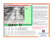
Routing Each Phase to a BIU Detector Channel Using SVS Relay Interface Cards 1 3 2 4 5 1 1) Click the Clear All Detector Routing Check Boxes button to clear all of the right side routing check boxes. Click the Detector Interface field to select BIU# 1-CardFile. 2) Click in the Relays per SVS-RI Card field to select the number of relays per card. 3) Click in the Det Main/Aux SVS-RI Slot # fields to select the card file slots to use.
Routing Each Phase to SVS Relay Interface Card Edges for a Type 170 Card file 1 2 3 4 1 1) Click the Clear All Detector Routing Check Boxes button to clear all of the right side routing check boxes. Click the Detector Interface field to select T-170-CardFile. 2) Click in the Relays per SVS-RI Card field to select the number of Relays per card. 3) Note that choosing the Detector Interface as Type 170 reveals the card edge signals (F, W, S, Y) available for use.
Routing Each Phase to a BIU-SDLC Detector Channel 1 3 2 1 1) Click the Clear All Detector Routing Check Boxes button to clear all of the right side routing check boxes. Click the Detector Interface field to select BIU# 1-SDLC. 2) Click each routing check box (right side check boxes) to specify which Phases will be combined (Or’ed or And’ed) and routed to each Detector Channel. 3) Click in each Detector Channel field to specify the BIU detector channel (D01 to D16).
Closing Setup Windows and Saving Setup Parameters After assigning/reviewing Detection Line Zones to Phases and then routing them to a Detector Channel, click the OK button on the Detector Line Zone Mapping window to capture the settings and close the window. Next, click the OK button on the Detection Zone Setup window to capture the settings and close the window. Note that these settings must be sent to the corresponding SVS-1 camera processing channel (SVS0001, SVS0002, etc.
SVS-1 – Sending Parameters to a Specific SVS-1 Camera Processing Channel (SVS ID) After setting up all Line Zones, Circle Zones, the Light Reference Parameters, and the Detection Zones to Relay Mapping, settings must be sent to the corresponding SVS-1 camera processing channel (SVS0001, SVS0002, etc.) to remove the yellow parameter mismatch warning flag. Use SVS/Send SVS Parameters menu item.
SVS-1 Banner Display From the SVS main display, click the Settings/Visible Message Window menu item to open the message window. Then click the SVS/Get Banner menu item. This display shows the SVS-1 Current ID, the Processing Hardware Revision Number and the current Software Version Number.
SVS-1 – Detection Zone Sensitivity Parameters The sensitivity parameters for each Line Zone and associated Circle Zone are displayed to the right of the camera image. Choose a zone by clicking 1 of 30 option buttons in the Zone Select Frame (below the image). The following sections provide detailed descriptions for each of the Line Zone/Circle Zone parameters. Detection Threshold – Specifies Line Zone detection sensitivity and may be adjusted by changing the Detection Threshold value .
SVS-1 – Detection Zone Sensitivity Parameters (continued) No Motion Timeout – Specifies the amount of time in minutes that must pass in the absence of detectable motion before the system samples the Line Zone pixel values to test and update the Line Zone background. The value for this parameter must be greater than the amount of time vehicles sit stationary at a red traffic light. The default value for this parameter is 1 minute.
SVS-1 – Setting Detection Zone Sensitivity Parameters (continued) Circle Zone Radius– Specifies the size of the Circle Detection Zone. The circle zone is located at the up road end of the corresponding Line Detection Zone and is used as part of the directional detection criterion. The Circle Zone size is dependent on the specific image of the intersection stop line area. The Circle Zone radius should be chosen so that it’s diameter is approximately 1/5 the width of the lane it resides in.
SVS-1 – Setting Light Reference Parameters and Visibility Parameters The parameters for the Light and Visibility Reference are displayed to the right of the camera image. Choose the Light Reference by clicking LR option button in the Zone Select Frame (below the image). The following section provides detailed descriptions for each of the Light Reference and Visibility parameters.