The SmarTek Video Detection System (SVS-1) User Guide-Part E Using a Mouse and Monitor to Setup the SVS-1 05 May 2011
Setting up the SVS-1 using a Mouse and Video Monitor (No PC Required) Overview. The SVS-1 processor cards may be setup using only an NTSC video monitor connected to the “Out” BNC jack and a mouse connected to the USB port or the serial RJ-45 jack. This section describes the setup procedure using only a video monitor and mouse.
Mouse and Monitor SVS-1 Setup (No PC Required) Plug Mouse into Serial or USB Port Top Level Video Out Display Click Setup Main Setup Display - Click Init BG to Initialize All LZ Backgrounds - Click Reset Card to Reset the SVS-1 Processor Click Draw LZs Click Set Output Click Set LZ Pars Click Set Display Click Get Banner Draw Line Zones Display Set Output Display Set Line Zone Parameters Display Set Video Out Text Display Banner Display - Draw LZs - Group LZs into Phases (1L, 6T, etc.
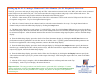
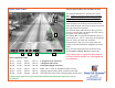
Top Level and Main Setup Displays After connecting the mouse, the Top Level navigation buttons appear on the output video image. From the display, the user may manually initialize line zone backgrounds if line zones have already been setup or the user may reset the processor, or the user may proceed to the main setup display by clicking the Setup button. If an SVS-1 multi-camera channel processor is being used, clicking the Camera button will select the camera channel to be set up.
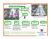
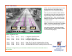
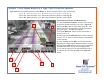
Draw Line Zones Set Line Zone Position, Size and Phase Group: 2 1 3 4 6 Phase assignment Codes: 1) Click the LZ# button to select the line zone to draw. If the previous line zone has been assigned a phase, right clicking anywhere on the display will assign that phase to the currently selected line zone. 2) Draw the Line Zone position by left clicking (hold down left button) at the down road end of the Line Zone and drawing the Line Zone to the up road end (at this end, release the left button).
Draw Line Zones SVS-1 detection is directional, hence be sure the direction arrow on each line zone is pointed in the correct direction of travel. The “Up” arrow beside the “Main” button provides for moving the setup buttons to the top of the image if they are in in the way of drawing line zones. After moving the setup buttons to the top, the “Up” arrow becomes a “Down” arrow. The selected line zone is shown in green, all others are shown in magenta (show in output video) or gray (not show in output video).
Set Line Zone Parameters 3 4 2 1 4 No Motion Timeout (default=2 min) – This should be set as close to the light cycle time as possible Rural intersections might be 1 min while urban intersections might be as long as 3 or 4 minutes. Detection Threshold (default=8) – Increasing this threshold decreases detection sensitivity, while decreasing this threshold increases sensitivity. Values range from 5 to 12.
Setting Output - Example Scenario Summary From the Main Setup display, proceed to the Set Output display by clicking the Set Output button. This display is used to specify the detector interface type , combine phases into vehicle presence relays, and then route them to output detector channels. After setting up the output relay signals, return to the Main Setup display by clicking the Main button.
Setting Output Example Scenario Summary (Continued) 4) BIU #1 Card file Detector/Controller Interface with 4 Relays per SVS-1 card, Slot 4 used, and 3 Phases (Line Zone Groups) Phase 3L, Detection Delay=0 sec, Detection Extension=0, Route to Detector Channel D5 Phase 8T, Detection Delay=0 sec, Detection Extension=0, Route to Detector Channel D6 Phase 8R, Detection Delay=2 sec, Detection Extension=2, Route to Detector Channel D6 Note: This scenario would be a typical dual camera input to a 2 camera SVS-1 Ca
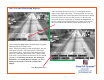
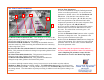
Scenario 1 Set 4 Output Relays For a Type 170/2070 Card File Interface Type-170 Detector/Controller Interface with 4 Relays per SVS-1 card and 3 Phases (Line Zone Groups) Phase 1L, Detection Delay=0 sec, Detection Extension=0, Route to Card Edge F Phase 6T, Detection Delay=0 sec, Detection Extension=0, Route to Card Edge W Phase 6R, Detection Delay=2 sec, Detection Extension=0, Route to Card Edge W 4 7 1 5 3 6 2 Select Detector Interface and Route Relays: 1) Click the Detector Interface button to selec
Scenario 1 (Con’t) Set 4 Output Relays For a Type 170/2070 Card File Interface Type-170 Detector/Controller Interface with 4 Relays per SVS-1 card and 3 Phases (Line Zone Groups) Phase 1L, Detection Delay=0 sec, Detection Extension=0, Route to Card Edge F Phase 6T, Detection Delay=0 sec, Detection Extension=0, Route to Card Edge W Phase 6R, Detection Delay=2 sec, Detection Extension=0, Route to Card Edge W 4 7 1 5 3 6 2 Select Detector Interface and Route Relays: 1) Click the Detector Interface button
Scenario 1 (Con’t) Set 4 Output Relays For a Type 170 Card File Interface Type-170 Detector/Controller Interface with 4 Relays per SVS-1 card and 3 Phases (Line Zone Groups) Phase 1L, Detection Delay=0 sec, Detection Extension=0, Route to Card Edge F Phase 6T, Detection Delay=0 sec, Detection Extension=0, Route to Card Edge W Phase 6R, Detection Delay=2 sec, Detection Extension=0, Route to Card Edge W 4 7 1 5 3 6 2 Select Detector Interface and Route Relays: 1) Click the Detector Interface button to sel
Scenario 2 Set 2 Output Relays per Card for a 170/2070 Controller Type-170 Detector/Controller Interface with 2 Relays per SVS-1 card and 3 Phases (Line Zone Groups) Phase 1L, Detection Delay=0 sec, Detection Extension=0, Route to Card Edge F Phase 6T, Detection Delay=0 sec, Detection Extension=0, Route to Card Edge W Phase 6R, Detection Delay=2 sec, Detection Extension=0, Route to Card Edge W 4 7 1 5 3 6 2 Select Detector Interface and Route Relays: 1) Click the Detector Interface button to select the
Scenario 2 (Con’t) Set 2 Output Relays per Card for a 170/2070 Controller Type-170 Detector/Controller Interface with 2 Relays per SVS-1 card and 3 Phases (Line Zone Groups) Phase 1L, Detection Delay=0 sec, Detection Extension=0, Route to Card Edge F Phase 6T, Detection Delay=0 sec, Detection Extension=0, Route to Card Edge W Phase 6R, Detection Delay=2 sec, Detection Extension=0, Route to Card Edge W 4 7 1 5 3 6 2 Select Detector Interface and Route Relays: 1) Click the Detector Interface button to se
Scenario 2 (Con’t) Set 2 Output Relays per Card for a 170/2070 Controller Type-170 Detector/Controller Interface with 2 Relays per SVS-1 card and 3 Phases (Line Zone Groups) Phase 1L, Detection Delay=0 sec, Detection Extension=0, Route to Card Edge F Phase 6T, Detection Delay=0 sec, Detection Extension=0, Route to Card Edge W Phase 6R, Detection Delay=2 sec, Detection Extension=0, Route to Card Edge W 4 7 1 5 3 6 2 Select Detector Interface and Route Relays: 1) Click the Detector Interface button to se
Scenario 3 Set 4 Output Relays to BIU #1 Card File BIU #1 Card file Detector/Controller Interface with 4 Relays per SVS-1 card, Slot 2 used, and 3 Phases (Line Zone Groups) Phase 3L, Detection Delay=0 sec, Detection Extension=0, Route to Detector Channel D1 Phase 8T, Detection Delay=0 sec, Detection Extension=0, Route to Detector Channel D2 Phase 8R, Detection Delay=2 sec, Detection Extension=2, Route to Detector Channel D2 4 7 3 1 5 6 2 Select Detector Interface and Route Relays: 1) Click the Detector
Scenario 3 (Con’t) Set 4 Output Relays to BIU #1 Card File BIU #1 Card file Detector/Controller Interface with 4 Relays per SVS-1 card, Slot 2 used, and 3 Phases (Line Zone Groups) Phase 3L, Detection Delay=0 sec, Detection Extension=0, Route to Detector Channel D1 Phase 8T, Detection Delay=0 sec, Detection Extension=0, Route to Detector Channel D2 Phase 8R, Detection Delay=2 sec, Detection Extension=2, Route to Detector Channel D2 4 7 3 1 5 6 2 Select Detector Interface and Route Relays: 1) Click the
Scenario 3 (Con’t) Set 4 Output Relays to BIU #1 Card File BIU #1 Card file Detector/Controller Interface with 4 Relays per SVS-1 card, Slot 2 used, and 3 Phases (Line Zone Groups) Phase 3L, Detection Delay=0 sec, Detection Extension=0, Route to Detector Channel D1 Phase 8T, Detection Delay=0 sec, Detection Extension=0, Route to Detector Channel D2 Phase 8R, Detection Delay=2 sec, Detection Extension=2, Route to Detector Channel D2 4 7 3 1 5 6 2 Select Detector Interface and Route Relays: 1) Click the
Scenario 4 Set 4 Output Relays to BIU #1 Card File BIU #1 Card file Detector/Controller Interface with 4 Relays per SVS-1 card, Slot 4 used, and 3 Phases (Line Zone Groups) Phase 3L, Detection Delay=0 sec, Detection Extension=0, Route to Detector Channel D5 Phase 8T, Detection Delay=0 sec, Detection Extension=0, Route to Detector Channel D6 Phase 8R, Detection Delay=2 sec, Detection Extension=2, Route to Detector Channel D6 4 7 3 1 5 6 2 Select Detector Interface and Route Relays: 1) Click the Detector
Scenario 4 (Con’t) Set 4 Output Relays to BIU #1 Card File BIU #1 Card file Detector/Controller Interface with 4 Relays per SVS-1 card, Slot 4 used, and 3 Phases (Line Zone Groups) Phase 3L, Detection Delay=0 sec, Detection Extension=0, Route to Detector Channel D5 Phase 8T, Detection Delay=0 sec, Detection Extension=0, Route to Detector Channel D6 Phase 8R, Detection Delay=2 sec, Detection Extension=2, Route to Detector Channel D6 4 7 3 1 5 6 2 Select Detector Interface and Route Relays: 1) Click the
Scenario 4 (Con’t) Set 4 Output Relays to BIU #1 Card File BIU #1 Card file Detector/Controller Interface with 4 Relays per SVS-1 card, Slot 4 used, and 3 Phases (Line Zone Groups) Phase 3L, Detection Delay=0 sec, Detection Extension=0, Route to Detector Channel D5 Phase 8T, Detection Delay=0 sec, Detection Extension=0, Route to Detector Channel D6 Phase 8R, Detection Delay=2 sec, Detection Extension=2, Route to Detector Channel D6 4 7 3 1 5 6 2 Select Detector Interface and Route Relays: 1) Click the
Scenario 5 Set 2 Output Relays to BIU #1 Card File BIU #1 Card file Detector/Controller Interface with 2 Relays per SVS-1 card, Slot 2 used, and 3 Phases (Line Zone Groups) Phase 3L, Detection Delay=0 sec, Detection Extension=0, Route to Detector Channel D1 Phase 8T, Detection Delay=0 sec, Detection Extension=0, Route to Detector Channel D2 Phase 8R, Detection Delay=2 sec, Detection Extension=2, Route to Detector Channel D2 4 7 3 1 5 6 2 Select Detector Interface and Route Relays: 1) Click the Detector
Scenario 5 (Con’t) Set 2 Output Relays to BIU #1 Card File BIU #1 Card file Detector/Controller Interface with 2 Relays per SVS-1 card, Slot 2 used, and 3 Phases (Line Zone Groups) Phase 3L, Detection Delay=0 sec, Detection Extension=0, Route to Detector Channel D1 Phase 8T, Detection Delay=0 sec, Detection Extension=0, Route to Detector Channel D2 Phase 8R, Detection Delay=2 sec, Detection Extension=2, Route to Detector Channel D2 4 7 3 1 5 6 2 Select Detector Interface and Route Relays: 1) Click the
Scenario 5 (Con’t) Set 2 Output Relays to BIU #1 Card File BIU #1 Card file Detector/Controller Interface with 2 Relays per SVS-1 card, Slot 2 used, and 3 Phases (Line Zone Groups) Phase 3L, Detection Delay=0 sec, Detection Extension=0, Route to Detector Channel D1 Phase 8T, Detection Delay=0 sec, Detection Extension=0, Route to Detector Channel D2 Phase 8R, Detection Delay=2 sec, Detection Extension=2, Route to Detector Channel D2 4 7 3 1 5 6 2 Select Detector Interface and Route Relays: 1) Click the
Scenario 6 Set Output Relays For SDLC output from BIU#1 BIU #1 SDLC Detector/Controller Interface with 3 Phases (Line Zone Groups) Phase 5L, Detection Delay=0 sec, Detection Extension=0, Route to Detector Channel D7 Phase 2T, Detection Delay=0 sec, Detection Extension=0, Route to Detector Channel D8 Phase 2R, Detection Delay=2 sec, Detection Extension=0, Route to Detector Channel D8 3 76 1 4 5 2 Select Detector Interface and Route Relays: 1) Click the Detector Interface button to select the type of dete
Scenario 6 (Con’t) Set Output Relays For SDLC output from BIU#1 BIU #1 SDLC Detector/Controller Interface with 3 Phases (Line Zone Groups) Phase 5L, Detection Delay=0 sec, Detection Extension=0, Route to Detector Channel D7 Phase 2T, Detection Delay=0 sec, Detection Extension=0, Route to Detector Channel D8 Phase 2R, Detection Delay=2 sec, Detection Extension=0, Route to Detector Channel D8 3 76 1 4 5 2 Select Detector Interface and Route Relays: 1) Click the Detector Interface button to select the type
Scenario 6 (Con’t) Set Output Relays For SDLC output from BIU#1 BIU #1 SDLC Detector/Controller Interface with 3 Phases (Line Zone Groups) Phase 5L, Detection Delay=0 sec, Detection Extension=0, Route to Detector Channel D7 Phase 2T, Detection Delay=0 sec, Detection Extension=0, Route to Detector Channel D8 Phase 2R, Detection Delay=2 sec, Detection Extension=0, Route to Detector Channel D8 3 76 1 4 5 2 Select Detector Interface and Route Relays: 1) Click the Detector Interface button to select the type
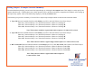
Set Output Video Text Display This display is used to enter descriptive text which may be set to show on the output video image. Upon opening this display, click the (1) Edit button to show a virtual keyboard for text entry. The Edit button changes to Enter. When finished entering text, click (2) Enter to capture the text. Click and hold on the (3) text label to drag it to the desired position. The X= and Y= labels show the position in pixels.
SVS-1 Banner Display This display shows the SVS-1 Current ID, the Processing Hardware Revision Number and the current Software Version Number. Click the Main button to return to the Main Setup display.