In-LineLinc Relay Owners Manual INSTEON® In-LineLinc On/Off, Dual-Band (#2475SDB) Page 1 of 12 2475SDB - Rev: 1/21/2014 7:58 AM
About In-LineLinc Relay ............................................................................................................................. 3 Features & Benefits .................................................................................................................................... 3 What’s in the Box? ..................................................................................................................................... 4 Installation .....................................
About In-LineLinc Relay In-LineLinc can be installed in-line for lighting fixtures, providing INSTEON control to individual fixtures. Additionally, In-LineLinc eliminates the need for a conventional light switch – reducing “switch sprawl” common to automation projects. You can also use In-LineLinc as an INSTEON signal repeater and phase bridger (like an Access Point, #2443).
What’s in the Box? In-LineLinc Four (4) wire nuts Quick-Start Guide Installation CAUTIONS AND WARNINGS Read and understand these instructions before installing and retain them for future reference. In-LineLinc is intended for installation in accordance with the National Electric Code and local regulations in the United States or the Canadian Electrical Code and local regulations in Canada. Use indoors only. In-LineLinc is not designed nor approved for use on power lines other than 120VAC-277VAC 60Hz.
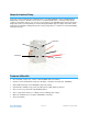
2) At the circuit breaker or fuse panel, disable the circuit supplying power to the fixture, and then verify the power is off 3) Remove the wallplate from the fixture you’ll be replacing. Then, unscrew the fixture itself and pull it out from the junction box. 4) Disconnect the wires from the fixture you will be controlling and ensure that you have ½ inch of bare wire on the ends. 5) See the diagram below to identify and connect the LINE, LOAD, NEUTRAL, and GROUND wires on In-LineLinc.
INSTEON Scenes Scene Definition: One or more INSTEON devices that respond to an INSTEON controller. When the scene is activated (turned “on”), all devices return to the states they were at when the scene was programmed. Adding In-LineLinc to a Scene as a Responder 1) Use the On and Off button on In-LineLinc to set the load to the state you wish to activate from the controller (turn it on if you wish it to be on when the controller activates the scene, etc.
Advanced Features Using In-LineLinc as a Phase Bridge (Phase Bridging Detection Mode) In-LineLinc automatically bridges the electrical phases in your home (via communications with dual-band devices on the “other phase”).
Resetting In-LineLinc to its Factory Default Settings The factory reset procedure clears all settings from In-LineLinc, including INSTEON links, X10 addresses, etc. Option 1 1) If possible, remove all scene memberships prior to performing the factory reset.
Specifications General Product Name In-LineLinc Relay – INSTEON Remote Control In-Line On/Off Switch (Dual-Band) Brand Smarthome Manufacturer Product Number 2475SDB UPC 813922011425 FCC ID SBP4773 Patent Number 7,345,998 US, International Patents Pending Warranty 2 Years, Limited INSTEON INSTEON ID 1 INSTEON 256 responder groups & 1 controller group Maximum Scene Links 417 Scene Commands Supported as Responder On Software Configurable Yes, Always RF Range 150’ Open air X10 Support
Operating Humidity Range 0-85% Relative Humidity Electrical 120VAC +/- 10%, Split, Single Phase Voltage 240VAC +/- 10%, Single Phase 277VAC +/- 10% Three Phase Frequency 60Hz Maximum Load 20 Amps;1800 Watts (for incandescent loads) Load Type(s) Wired-in incandescent lighting and inductive loads Retains all settings without power Yes, all saved in Non-volatile EEPROM Standby power consumption < 1 watt Safety Approved ETL (Intertek Testing Services) Certifications FCC, IC Canada X10 Features
Problem In-LineLinc is taking a long time to respond to a controller. The load turned on by itself. Possible Cause Solution Other electrical devices, such as computers, televisions, or power strips, may be absorbing the INSTEON signal. The controller may be sending commands to a responder that is no longer in use. Commands for the unused responder are being resent and loading down the signal. Another controller or timer could have triggered InLineLinc.
The digital circuitry of this device has been tested and found to comply with the limits for a Class B digital device, pursuant to Part 15.107 and 15.109 of the FCC Rules. These limits are designed to provide reasonable protection against harmful interference in residential installations. This equipment generates, uses, and can radiate radio frequency energy and, if not installed and used in accordance with the instructions, may cause harmful interference to radio and television reception.