
User's Manual


Page 9 of 32 2474DWH- Rev: 3/6/2012 10:13 AM
- If you wish the load to be off when link is activated (such as for an “all off” scene), turn the load off in step #2
Make SwitchLinc a Controller
Follow the steps below to control a different INSTEON device from SwitchLinc.
1) Press & hold SwitchLinc set button until it beeps
SwitchLinc LED will start blinking green
2) Turn responder on
1
3) Press & hold responder set button until it double-beeps
SwitchLinc LED will stop blinking
2
Responder LED will stop blinking and (Beep)-(Beep)
3
5) Test by tapping SwitchLinc paddle on and off
Responder will toggle on and off
Notes:
- If you wish to add another responder, repeat steps 1-5
- The link just created is one-way, see “Make SwitchLinc a Responder” to add another link to keep the two
products in synch.
Groups (keeps devices synchronized)
Devices in a group will all remain synchronized. Every device in a group is a controller of all the other devices as
well as a responder of all the other devices. The most common example of a group is a 3-way lighting circuit (2
switches). For simplicity, we will assume that the desired group level is on.
Example of a 3 way circuit with switches “A” and “B”
1) Turn A and B on
2) Press & hold A set button until it beeps
A status LED will start blinking green
3) Press & hold B set button until it double-beeps
A will (Beep)-(Beep) and its LED will stop blinking
4) Press & hold B set button until it beeps
B LED will start blinking green
5) Press & hold A set button until it double-beeps
B will (Beep)-(Beep) and its LED will stop blinking
6) Test the group by controlling the load from A and then B
The load, A LED and B LED will remain in synch
Scenes
INSTEON scenes allow a controller to set the mood by setting multiple responders to any number of desired levels,
all simultaneously. Software is recommended when setting up and maintaining scenes.
Create a scene with 1 controller and SwitchLinc as a member
1) Press & hold controller button until beep
Controller LED will start blinking green
2) Tap controller set button
Controller LED will start double-blinking green
3) Tap SwitchLinc on & adjust to desired scene state
SwitchLinc LED will be white
4) Press & hold SwitchLinc set button until double-beep
5) For each additional scene member
a. Adjust member to desired scene brightness / state
b. Press & hold set button until double-beep
6) Press & hold controller set button until double-beep
Controller LED stops blinking
1
If the responder is a multi-Scene device such as a KeypadLinc, tap the Scene button you wish to control until its LED is in the desired Scene state (on or off). You can any state, not just on,
for the responder’s link.
2
If either the SwitchLinc or responders LED continues to blink, the addition failed. Tap the device’s Set button until LED stops blinking and try again.
3
If either the SwitchLinc or responders LED continues to blink, the addition failed. Tap the device’s Set button until LED stops blinking and try again.
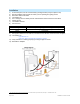
SwitchLinc
(Controller)
Responder
Link