On-Line Owner’s Manual Containing Cautionary FCC & IC Statements November 10, 2011 In-Line 0-10VDC Dimmer or Dual-Switch Model: 2475DA2 FCC ID: SBP2475DA2 IC: 5202A-2475DA2 The owner’s manual below may be accessed freely via the Internet with any web browser and supports the PDF format. www.smarthome.com/2475DA2.html Complies with Section 5 of FCC document 784748 D01 Labeling Part 15 18 Guidelines v07 where cautionary statements in the user manual may be provided over the Internet.
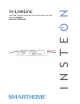
In-LineLinc INSTEON® Remote Control In-Line 0-10VDC Dimmer or Dual Switch (#2475DA2) Owners Manual Page 1 of 12 2475DA2 Rev: 11/10/2011 9:41 AM
In-LineLinc ................................................................................................................................................... 3 Features & Benefits .................................................................................................................................... 3 What’s in the Box?..................................................................................................................................... 3 Optional Accessories.....................
In-LineLinc The In-LineLinc Dimmer/Dual-Relay is an in-line INSTEON ballast control module that supports 2 different operational modes: Dimmer Mode and a Dual-Relay Mode. For use in new construction or retrofit (inside or outside the fixture) where saving energy is a priority.
Optional Accessories KeypadLinc Relay 2487S (100VAC-277VAC) KeypadLinc Dimmer (120VAC) Getting Started Map out the wall switch and load that you are going to remotely operate. Keep in mind that you are going to replace the existing wall switch with a KeypadLinc and wire both the KeypadLinc and the In-LineLinc to the same constant hot line using the existing wiring. Installing In-LineLinc CAUTIONS AND WARNINGS Read and understand these instructions before installing and retain them for future reference.
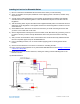
Installing In-LineLinc for Dimmable Ballast 1) Be sure to write down the INSTEON ID and location of the fixture you’ll be controlling 2) At the circuit breaker or fuse panel, disable the circuit supplying power to the fixture, and then verify the power is off 3) You will need to install a KeypadLinc 277V Controller (model 2487s) at the wall box that originally controlled the fixture. Wire the KeypadLinc to line and Neutral but cap the red Load wire from the KeypadLinc.
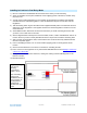
Installing In-LineLinc in Dual Relay Mode 1) Be sure to write down the INSTEON ID and location of the fixture you’ll be controlling 2) At the circuit breaker or fuse panel, disable the circuit supplying power to the fixture, and then verify the power is off 3) You will need to install a KeypadLinc 277V Controller (model 2487s) at the wall box that originally controlled the fixture. Wire the KeypadLinc to line and Neutral but cap the red Load wire from the KeypadLinc.
INSTEON Programming Links made between devices are called Scenes. The Scenes can contain 1 or 100+ devices Adding In-LineLinc to a Scene as a Responder 1) Use the On and Off button on In-LineLinc to set the load to the state you wish to activate from the controller (turn it on if you wish it to be on when the controller activates the scene, etc.
- If they are not blinking green 1 i. 3) Try moving the “other” device, check other dual-band devices or begin test from a different initiator Tap In-LineLinc’s Set Button In-LineLinc will stop beeping and LED returns to previous state Other devices’ LEDs will stop blinking Restoring Power to In-LineLinc In-LineLinc stores all of its settings, such as links to other INSTEON devices, with non-volatile memory.
Specifications General Product Name In-LineLinc Relay – INSTEON Remote Control In-Line On/Off Switch (Dual-Band) Brand Smarthome Manufacturer Product Number 2475SDB UPC 813922011425 FCC ID SBP4773 Patent Number 7,345,998 US, International Patents Pending Warranty 2 Years, Limited INSTEON INSTEON ID 1 INSTEON 256 responder groups & 1 controller group Maximum Scene Links 417 Scene Commands Supported as Responder On Software Configurable Yes, Always RF Range 150’ Open air X10 Support
Operating Temperature Range 40 - 132 degrees Fahrenheit Operating Humidity Range 0-85% Relative Humidity Electrical Voltage 100VAC to 277VAC (0-10VDC Dimmer) Frequency Supports 50 Hz / 60 Hz dedicated for international and US use Output lines (0-10VDC, Load 1 (277VAC / 5A), and load 2 (277VAC / 5A)) Maximum Load Load Type(s) Wired in ballasted dimming and non-dimming lighting loads Retains all settings without power Yes, all saved in Non-volatile EEPROM Standby power consumption < 1 watt Safet
Troubleshooting Problem Possible Cause The Status LED on InLineLinc is not turning In-LineLinc may not be on and won’t control getting power. the load. In-LineLinc won’t link or work with a controller. In-LineLinc is taking a long time to respond to a controller. The load turned on by itself. Solution Make sure the circuit breaker is turned on. Check the junction box wires to ensure all connections are tight and no bare wires are exposed.
Certification and Warranty Certification This product has been thoroughly tested by ITS ETL SEMKO, a nationally recognized independent third-party testing laboratory. The North American ETL Listed mark signifies that the device has been tested to and has met the requirements of a widely recognized consensus of U.S.