
User's Manual


Page 5 of 12 2475DA2 Rev: 11/10/2011 9:41 AM
Installing In-LineLinc for Dimmable Ballast
1) Be sure to write down the INSTEON ID and location of the fixture you’ll be controlling
ture, and then verify
need to install a KeypadLinc 277V Controller (model 2487s) at the wall box that originally
wire from the
e load and wire nut it
c and the In-LineLinc
ling and ensure that
have ½ inch of bare wire on the ends
d DC(-) wires on
before connecting
.
nnectors are firmly attached and that
he fixture, turn on circuit breaker supplying power to the KeypadLinc and In-
eLinc to test that it is controlling the load
10) Link In-LineLinc to the KeypadLinc or any other desired INSTEON devices. See Adding In-LineLinc to
2) At the circuit breaker or fuse panel, disable the circuit supplying power to the fix
the power is off
3) You will
controlled the fixture. Wire the KeypadLinc to line and Neutral but cap the red Load
KeypadLinc.
4) Take the existing switch leg from the wall box that supplied switched power to th
with the line on the KeypadLinc. This supplies constant HOT to both KeypadLin
at the same time
5) At the Ballast location, disconnect the wires from the fixture you will be control
you
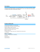
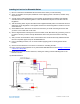
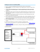
6) See the diagram below to identify and connect the LINE, LOAD, NEUTRAL DC(+) an
In-LineLinc. Be sure you have correctly identified the wires in the junction box
them
7) After you have connected all the wires, ensure that the wire co
there is no exposed copper except for the GROUND wire
8) Prior to reinstalling t
LineLinc
9) Use the On and Off button on In-Lin
a Scene as a Responder.
11) Gently place In-LineLinc into the fixture box, making sure nothing could accidentally press on the
buttons on its face
12) Reinstall the fixture