
User's Manual
2452-222/2452-422/2452-522 Rev. 8/13/2012 9:25 AM / See Owner’s Manual for Warranty Information.
Protected under U.S. and foreign patents (see www.insteon.com)
© Copyright 2012 INSTEON, 16542 Millikan Ave., Irvine, CA 92606, 800-762-7845
Quick Start Guide
INSTEON
®
DIN Rail Dimmer
Model: 2452-222/2452-422/2452-522
About INSTEON DIN Rail Dimmer
The compact INSTEON DIN Rail Dimmer module installs directly onto the DIN rail
to give you fully dimmable remote control over compatible lights.
Note:
Installation should only be performed by a qualified electrician or a
homeowner who is familiar and comfortable with electrical circuitry. If you have
questions, consult an electrician or call the INSTEON Support Line at 800-762-
7845.
In the Box
- INSTEON DIN Rail Dimmer
What’s Needed
- Flathead screwdriver - Wire cutter/stripper - Voltage meter
Before Installation
Before you install DIN Rail Module behind a switch, you must determine which switch operation mode applies to your
switch—latching, single momentary or dual momentary—as each is wired differently:
Latching (default mode): Switch has no central position. It can be tapped on both the top and bottom and
remains in that state once released.
Single momentary: Switch can only be tapped in one location. It returns to central position once released.
Dual momentary: Switch can be tapped on both the top and bottom. It returns to central position once
released.
Once you have identified your switch type, install DIN Rail module according to the corresponding wiring diagram,
then see “Switch Operation Mode” to program DIN Rail module for your specific switch type.
Install INSTEON DIN Rail Dimmer
1) Turn off breaker/fuse and verify that the power is off
2) At the DIN rail, strip away wire coating until you have 10mm (1/3”) of bare wire on the ends
3) After ensuring the wires are not touching, turn on breaker/fuse
4) Use a voltage meter to identify the fixture’s line, load and neutral wires, then turn off breaker/fuse again
5) For reference, write down the INSTEON I.D. (on the side of the module) and the load it is controlling
6) Snap module onto DIN rail. (If installing next to another module, allow 2cm between modules for heat
dissipation.)
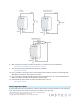
7) Connect line, load, neutral and sense wires according to the diagram corresponding to your switch type:
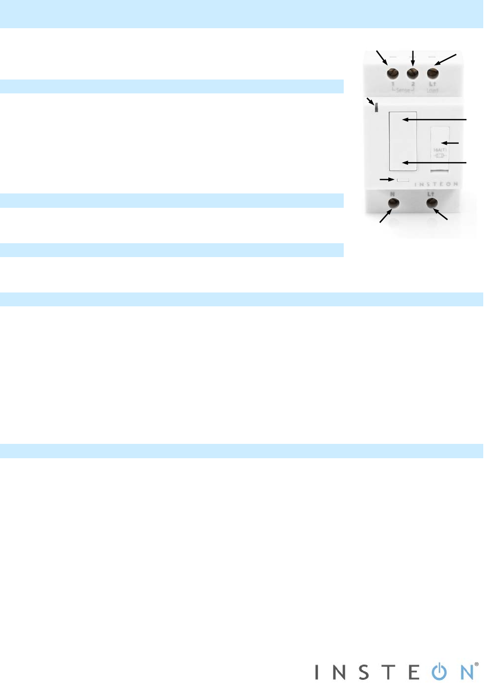
Neutral
Line
LED
Set
button
Sense #2
Connected
load
Sense #1
Paddle top
(on/brighten)
Fuse
Paddle bottom
(off/dim)