
User's Manual
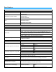
Table Of Contents
- About Micro On/Off
- Before Installation
- Identifying the Electrical Wires in Your Home (North America only)
- Identifying the Electrical Wires in Your Home (Europe/Australia/New Zealand)
- Installation
- Switch Operation Mode
- 3-Way Toggle Mode (Latching Switches Only, Default)
- Local Control Operation
- Adjust Local Settings
- INSTEON Setup
- INSTEON Controllers, Responders and Links
- Configure INSTEON Settings
- Make Micro Module a Responder (Set button)
- Make Micro Module a Responder (Switch)
- Make Micro Module a Controller (Set button)
- Make Micro Module a Controller (Switch)
- Groups
- Scenes
- Make Micro Module a Controller of Multiple Responders
- Remove Micro Module as a Controller
- Remove Micro Module as a Responder
- Remove Micro Module as a Controller of Multiple Responders
- Factory Reset
- X10 Setup
- Specifications
- Troubleshooting
- Certification and Warranty
- Certification
- FCC and Industry Canada Compliance Statement
- The digital circuitry of this device has been tested and found to comply with the limits for a Class B digital device, pursuant to Part 15B of the FCC Rules. These limits are designed to provide reasonable protection against harmful interference in re...
- WARNING: Changes or modifications to this device not expressly approved by the party responsible for compliance could void the user’s authority to operate the equipment.
- Cet appareil a été testé et s’avère conforme aux restrictions relatives aux équipements numériques de classe B, d’après l’article 15 des règlements du Conseil supérieur de l’audiovisuel américain (FCC). Ces restrictions ont été instaurées pour offrir ...
- • Éloignez l’appareil du composant qui reçoit les ondes. • Branchez l’appareil dans une prise de courant CA différente de celle du composant qui reçoit les ondes. • Au besoin, consultez votre marchand électronique ou un technicien spécialisé dans le s...
- Declaration of Conformity
- ETL/UL Warning (Safety Warning)
- Limited Warranty
- Limitations

Page 11 of 21 2443-222/2443-422/2443-522 - Rev: 9/24/2014 12:46 PM
Groups
Devices in a group share all the same settings (e.g., on-level, ramp rate). This keeps all group members
synchronized. Every device in a group is both a controller of, and responder to, all the other devices. The most
common example of a group is a 3-way lighting circuit (2 switches). For simplicity, we will assume that the desired
group level is on.
The following steps will create a virtual 3-way circuit including device “A” and device “B”:
1) Turn A and B on
2) Press and hold A Set button until it beeps
A status LED will start blinking green
3) Press and hold B Set button until it double-beeps
A will double-beep and its LED will stop blinking
4) Press and hold B Set button until it beeps
B LED will start blinking green
5) Press and hold A Set button until it double-beeps
B will double-beep and its LED will stop blinking
6) Test by turning load on and off from A and then B
The load(s) and both A and B LEDs will remain in synch
Scenes
Devices in a scene can each have different settings. This provides for advanced scene creation. Software is
recommended for scene management.
Example of a scene with 1 controller and Micro module as a member:
1) Press and hold controller button until it beeps
Controller LED will start blinking green
2) Tap controller Set button
Controller LED will start double-blinking green
3) Adjust load to desired scene state (on or off)
4) Press and hold Micro module Set button until it double-beeps
5) For each additional scene member:
a. Adjust member to desired scene state
b. Press and hold Set button until it double-beeps
6) Tap controller Set button
Controller will beep and LED will stop blinking
7) Test by tapping controller button on and off
Micro module and other scene responders will all respond appropriately
Make Micro Module a Controller of Multiple Responders
1) Press and hold Micro module Set button until it beeps
LED will start blinking green
2) Tap Micro module Set button
LED will start double-blinking green
3) For each responder you are adding:
a. Adjust responder to desired scene state
b. Press and hold Set button until it double-beeps
4) Tap Micro module Set button
Micro module will beep and LED will stop blinking
5) Test by tapping switch wired into Micro module on and off
All the responders will turn on and off