
User's Manual
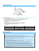
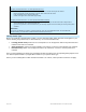
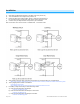
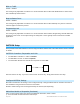
Table Of Contents
- About Micro On/Off
- Before Installation
- Identifying the Electrical Wires in Your Home (North America only)
- Identifying the Electrical Wires in Your Home (Europe/Australia/New Zealand)
- Installation
- Switch Operation Mode
- 3-Way Toggle Mode (Latching Switches Only, Default)
- Local Control Operation
- Adjust Local Settings
- INSTEON Setup
- INSTEON Controllers, Responders and Links
- Configure INSTEON Settings
- Make Micro Module a Responder (Set button)
- Make Micro Module a Responder (Switch)
- Make Micro Module a Controller (Set button)
- Make Micro Module a Controller (Switch)
- Groups
- Scenes
- Make Micro Module a Controller of Multiple Responders
- Remove Micro Module as a Controller
- Remove Micro Module as a Responder
- Remove Micro Module as a Controller of Multiple Responders
- Factory Reset
- X10 Setup
- Specifications
- Troubleshooting
- Certification and Warranty
- Certification
- FCC and Industry Canada Compliance Statement
- The digital circuitry of this device has been tested and found to comply with the limits for a Class B digital device, pursuant to Part 15B of the FCC Rules. These limits are designed to provide reasonable protection against harmful interference in re...
- WARNING: Changes or modifications to this device not expressly approved by the party responsible for compliance could void the user’s authority to operate the equipment.
- Cet appareil a été testé et s’avère conforme aux restrictions relatives aux équipements numériques de classe B, d’après l’article 15 des règlements du Conseil supérieur de l’audiovisuel américain (FCC). Ces restrictions ont été instaurées pour offrir ...
- • Éloignez l’appareil du composant qui reçoit les ondes. • Branchez l’appareil dans une prise de courant CA différente de celle du composant qui reçoit les ondes. • Au besoin, consultez votre marchand électronique ou un technicien spécialisé dans le s...
- Declaration of Conformity
- ETL/UL Warning (Safety Warning)
- Limited Warranty
- Limitations

Page 5 of 21 2443-222/2443-422/2443-522 - Rev: 9/24/2014 12:46 PM
Installation
1) Write down the INSTEON ID found on the back of the unit (XX.XX.XX)
2) Turn off breaker/fuse and verify that the power is off
3) Disconnect wires from existing switch, fixture or outlet and prep all wires to
be connected to Micro module, with 3/16” (5mm) of bare wire on the ends
4) Connect wires per diagram which corresponds to your installation
Note: sense lines carry very low current (~0.35mA 240V, ~0.17mA for 120V)
5) After ensuring wires are firmly connected and that there is no exposed wire, turn on breaker/fuse
After a few seconds, load will turn on (if wired into switch or fixture) and Micro module LED will turn green
6) Test by tapping Micro module on/off buttons
Load will turn on and off
Micro Module LED will turn green when load is on and red when load is off
7) If installing a single momentary or dual momentary switch
a) Press and hold set button until it beeps
LED will start blinking green
b) Press and hold set button until it beeps a second time
LED will start blinking red
c) Press and hold set button until it beeps a third time
LED will start blinking green