Micro Open/Close Owner’s Manual 2444-222 (US) 2444-422 (EU) 2444-522 (AUS/NZ) North America EU/AUS/NZ Page 1 of 21 2444-222/2444-422/2444-522 - Rev: 9/24/2014 12:47 PM
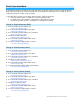
About Micro Open/Close .......................................................................................................................... 4 Features and Benefits ............................................................................................................................. 4 Before Installation.....................................................................................................................................
Limitations .............................................................................................................................................
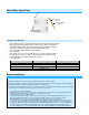
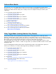
About Micro Open/Close LED Sense #1 (up) (yellow) Sense #2 (down) (purple) Antenna (secured for shipping purposes) Features and Benefits - Two integrated relays specifically designed for two-direction motorized devices Wires in behind existing wall switch in a fixture box (requires neutral wire) Compatible with latching, single momentary and dual momentary switches Sense wires allow local control from any standard wall switch Can contain up to 400 controller/responder links X10 compatible All settings p
DIMMING AN INDUCTIVE LOAD.
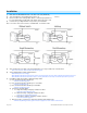
Installation 1) 2) 3) Write down the INSTEON ID found on the back of the unit (XX.XX.XX) Turn off breaker/fuse and verify that the power is off Disconnect wires from existing switch, fixture or outlet and prep all wires to be connected to Micro module, with 3/16” (5mm) of bare wire on the ends 4) Connect wires per diagram which corresponds to your installation Note: sense lines carry very low current (~0.35mA 240V, ~0.
Switch Operation Mode By default, Micro module is programmed for a latching switch. Program the switch operation for single momentary mode, dual momentary mode or back to latching mode according to your switch type. These settings can also be configured remotely via software (sold separately).
Calibrate Micro Module Once wired in, you need to calibrate Micro module for the time it takes for your application—shutters, blinds, projector screens, etc.—to fully raise/lower or open/close. Do not walk away during the calibration process as your Set button taps will determine the timing. These settings can also be configured remotely via software (sold separately).
Reverse Motor Direction For some applications, such as a projector screen, you want the connected motor to lower or close your connected screen or blinds when you press the up button or send an on command. Or you may have accidentally wired Micro module into the motor wrong. However, you don’t have to rewire Micro module to fix it. Follow these steps to reverse the motor direction in response to commands (i.e., an on command will close/lower while an off command will open/raise).
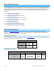
Dual Momentary Wall Switch Dual momentary switch Connected load/responders Tap Press and hold Double-tap LED Up Top Up/On (ramped) Up/On Brighten until release or 100% (dimmable responders only) Green (instant) Down Bottom Down/Off (ramped) Down/Off Dim until release or off (dimmable responders only) Red (instant) Adjust Local Settings Change LED Brightness (or turn it off) Default = 50% brightness level 1) Press and hold Set button until it beeps LED will start blinking green 2) Press and ho
This setting is only adjustable via software or a central controller. Micro module will beep every time its connected switch is tapped or a button is pressed. INSTEON Setup Some products have subtle differences in their setup procedures. Please refer to the other devices’ owner’s manuals for details.
Micro module will double-beep Controller will double-beep and its LED will stop blinking 4) Test link by tapping controller button on and off Load connected to Micro module will turn on and off Make Micro Module a Controller (Set button) Note: you must perform these steps before reinstalling the wall switch or fixture.
Scenes Devices in a scene can each have different settings. This provides for advanced scene creation. Software is recommended for scene management.
LED will start blinking red 3) Press and hold Micro module Set button until it double-beeps Controller LED will stop blinking 4) Test by tapping controller button on and off Micro module will no longer respond Remove Micro Module as a Controller of Multiple Responders 1) Press and hold Micro module Set button until it beeps LED will start blinking green 2) Press and hold Micro module Set button until it beeps again LED will start blinking red 3) Tap Micro module Set button LED will start double-blinking re
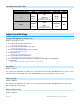
3) Send the X10 address 3 times (with or without commands) Example: A1-AOFF-A1-AOFF-A1-AOFF or A1-A1-A1-AOFF Micro module will double-beep and LED will stop blinking 4) Test by sending X10 on and off commands Micro module will not respond Specifications General Product name Micro Open/Close Brand / manufacturer INSTEON 2444-222 (US) Manufacturer product number 2444-422 (EU) 2444-522 (AUS/NZ) 813922012767 (US) UPC 813922012774 (EU) 813922012774 (AUS/NZ) Warranty 2 years, limited INSTEON INSTEON C
Phase detect beacon Yes X10 Support Yes X10 Addresses Any 1 of 256 (unassigned by default) INSTEON Device Category 0x0E Window Coverings (All Frequencies) INSTEON Device Subcategory 2444-222 (915 MHz) 0x01 2444-422 (869 MHz) 0x02 2444-522 (921 MHz) 0x03 Mechanical Mounting Wires Max Cable Size Min Cable Size Screw clamp connections Behind switch or outlet, or above light fixture in a single-gang electrical box Sense 1 (yellow wire), 0.205mm2 / 24 AWG Sense 2 (purple wire), 0.
Low voltage halogen Motor Hardwired remote control Yes, latching and momentary switches supported Retains all settings without power Yes, saved in non-volatile EEPROM Standby power consumption < 1 watt Safety approved ETL, CE, C-Tick FCC 15.107, 15.109, 15.249 RSS 210 Certifications EN 300 220-2, 301 489-3 AS/NZS 4268, CISPR 22 UL 1472 IEC 60669-2-1 FCC ID SBPMM01 All product specifications are subject to change.
Troubleshooting Problem Possible Cause Solution Make sure the circuit breaker is turned on The LEDs on Micro Micro module is not getting module are not turning on power at all Check junction box wires to ensure all connections are tight and no bare wires are exposed Check the motor to ensure all connections are tight and no bare wires are exposed I do not have a neutral wire Look in the rear of the junction box for a group of wires tied together with a wire nut.
Micro module still controls The responder’s link was not Remove responder from Micro module devices even after factory removed prior to Micro reset module factory reset (called a half-link) Stuck/Disabled Button If Micro module’s buttons are not responding, they may have been disabled due to a stuck button.
Certification and Warranty Certification This product has been thoroughly tested by ITS ETL SEMKO, a nationally recognized independent third-party testing laboratory. The North American ETL Listed mark signifies that the device has been tested to and has met the requirements of a widely recognized consensus of U.S.
Limited Warranty Seller warrants to the original consumer purchaser of this product that, for a period of two years from the date of purchase, this product will be free from defects in material and workmanship and will perform in substantial conformity to the description of the product in this Owner’s Manual. This warranty shall not apply to defects or errors caused by misuse or neglect.