
User's Manual


Page 6 of 21 2444-222/2444-422/2444-522 - Rev: 9/24/2014 12:47 PM
Installation
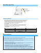
1) Write down the INSTEON ID found on the back of the unit (XX.XX.XX)
2) Turn off breaker/fuse and verify that the power is off
3) Disconnect wires from existing switch, fixture or outlet and prep all wires to
be connected to Micro module, with 3/16” (5mm) of bare wire on the ends
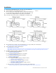
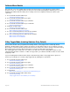
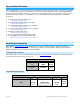
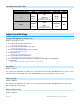
4) Connect wires per diagram which corresponds to your installation
Note: sense lines carry very low current (~0.35mA 240V, ~0.17mA for 120V)
5) After ensuring wires are firmly connected and that there is no exposed wire, turn on breaker/fuse
After a few seconds, Micro module LED will turn green
6) Test by tapping Micro module up/down buttons
Motor will respond accordingly
Micro Module LED will turn green when motor is moving up/open and stay green until the down button is pressed
Micro Module LED will turn red when motor is moving down/closed and stay red until the up button is pressed
7) If installing a single momentary or dual momentary switch
a) Press and hold set button until it beeps
LED will start blinking green
b) Press and hold set button until it beeps a second time
LED will start blinking red
c) Press and hold set button until it beeps a third time
LED will start blinking green
d) Perform the step that applies
• For single momentary: slowly tap set button four times
LED will continue blinking green
• For dual momentary: slowly tap set button five times
LED will start double-blinking green
• To switch back to latching: slowly tap set button six times
LED will start blinking green
e) Once the mode is selected, press and hold set button until it double-beeps
LED will stop blinking and turn green if motor is up/open or red if motor is down/closed
Antenna
Down
Up
Down
Up
Down
Up
Down
Up