
User's Manual


TRUGRD_Stream_User_Manual_USA_CAN_200MHz.docx Version 1 I Page 10 of 14 I February 8, 2021
UMRR based systems on the sensor CAN. The UMRR is compliant with CAN 2.0B standard.
CAN is a very robust full duplex bidirectional interface.
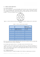
6.3 CAN-Settings
Baud Rate: 500 kBit/s or lower
T
seg1
: 8
T
seg2
: 7
T
sjw
: 2 (SJW: synchronization jump width)
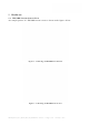
Above values for CAN bit timing are illustrated in Figure 6-2 used in the UMRR radar sensor
(note: the CAN module is integrated in the DSP). For comparison purposes, in Figure 6-3 the
CAN bit timing as defined by the CAN protocol is shown.
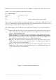
The CAN bit timing parts as defined by the CAN protocol (Figure 6-3) can be described as
follows:
• Sync: This part of bit time is used to synchronize the various nodes on the bus. An
edge is expected to lie within this segment. For the UMRR sensor, this segment is
always 1 TIME QUANTUM (TQ).
• Prop: This part of the bit time is used to compensate for the physical delay times
within the network. It is twice the sum of the signal’s propagation time on the bus
line, the input comparator delay, and the output driver delay. For the UMRR sensor,
this segment is programmable from 1 to 8 TIME QUANTA (TQ).
• Phase 1: This phase is used to compensate for positive edge phase error. For the
UMRR sensor, this segment is programmable from 1 to 8 TIME QUANTA (TQ) and
can be lengthened by resynchronization.
• Phase 2: This phase is used to compensate for negative edge phase error. For the
UMRR sensor, this segment is programmable from 2 to 8 TIME QUANTA (TQ) and
can be shortened by resynchronization.
Figure 6-2: CAN bit timing for UMRR sensor