
User's Manual


TRUGRD_Stream_User_Manual_USA_CAN_200MHz.docx Version 1 I Page 5 of 14 I February 8, 2021
4 General description
4.1 Sensor description
The main task of the UMRR is the detection of any reflectors in the field of view, to measure
the distance, the relative speed and the angle to the shortest reflector (and to other reflectors),
to detect motion and to track (filter) the results over time.
For this general purpose measurement application, range and relative radial speed and the
angle value of each reflector inside the antenna beam are measured and the results are
reported via the communication links cycle by cycle.
4.2 Transmit Signal
The UMRR transmit frequency is in the 24 GHz ISM band (24000 MHz to 24250 MHz) and the
used bandwidth is smaller than 250MHz.
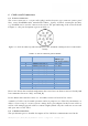
Antenna type 48 consists of 2 TX antennas with same antenna characteristics but different
center position on the board and 8 uniform RX antennas. The TX antenna have a 3dB antenna
beam width of +-34° in azimuth and +-6,5° in elevation. The 8 RX antennas have a 3dB
antenna beam width of +-25° in azimuth and +-7° in elevation. Highest TX antenna sidelobe:
@+74°, highest RX sidelobe at +-50°.
Note: max. Gain for TX antenna at azimuth angle +-22°, elevation angle 0°. The RX antennas
have max. gain at boresight.
Gain RX: 11.1 dBi.
The device uses different FMCW transmit signal waveforms for distance and speed
measurement.
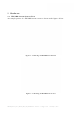
4.3 General Performance Data
After power up or reset, the sensor readings are within specified performance within <30
seconds. In Table 4-1 the general performance data is given.