SR804n Cable Modem User Manual VER: 1.
SR804n Cable Modem User Manual Contents 1 2 3 4 5 Safety Introductions ......................................................................................... 1 Overview ......................................................................................................... 2 2.1 Application .......................................................................................... 2 2.2 Features .............................................................................................. 2 2.
SR804n Cable Modem User Manual 5.4 5.5 5.6 5.7 5.8 5.9 5.3.4 Port Filtering ........................................................................... 24 5.3.5 Forwarding.............................................................................. 25 5.3.6 Port Triggers ........................................................................... 26 5.3.7 DMZ Host ............................................................................... 26 5.3.8 RIP Setup ........................................
SR804n Cable Modem User Manual 6 Q&A ..............................................................................................................
SR804N Cable Modem User Manual 1 Safety Introductions Read the following information carefully before operating the device. Please follow the following precaution items to protect the device from risks and damage caused by fire and electric power: Use volume labels to mark the type of power. Use the power adapter that is packed within the device package. Pay attention to the power load of the outlet or prolonged lines.
SR804N Cable Modem User Manual 2 Overview The SR804N is targeted towards DOCSIS/EuroDOCSIS3.0 cable modem, eMTA and gateway. With eight downstream channels and four upstream channels, it supports up to 400Mbs/160Mbs. The SR804N incorporates a variety of industry standard peripheral interfaces including dual IEEE802.3 10/100/1000Mbps interface, one with integrated GPHY, and dual USB2.0 interfaces(Host and Host/Device) with integrated PHYs. The SR804N supports WLAN access. It complies with IEEE 802.11,802.
SR804N Cable Modem User Manual 2.3 Remote update System statistics and monitoring Standards Compatibility and Compliance Support application level gateway (ALG) DOCSIS/EuroDOCSIS3.0 IEEE 802.3 IEEE 802.3u IEEE 802.11b IEEE 802.11g IEEE 802.
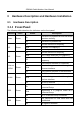
SR804N Cable Modem User Manual 3 Hardware Description and Hardware Installation 3.1 Hardware Description 3.1.1 Front Panel The following table describes the indicators on the front panel. Indicator Color Status Description Power D/S U/S Ethernet 1/2/3/4 WLAN WPS USB Green Green Green Green Green Green Green On The device is powered on and the device operates normally. Off The device is powered off.
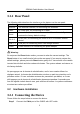
SR804N Cable Modem User Manual 3.1.2 Rear Panel The following table describes the interfaces or the buttons on the rear panel. Interface Description Antenna The antenna interface, for connecting the antennas. Cable RF cable port, for connecting HFC cable. Reset Press the button for at least 1 second and then release it. System restores the factory default settings. Eth 4~1 RJ-45 port, for connecting the router to a PC or another network device.
SR804N Cable Modem User Manual Step2 Step3 Connect the Eth port of the CMRG to the network card of the PC via an Ethernet cable. Plug one end of the power adapter to the wall outlet and connect the other end to the Power port of the CMRG.
SR804N Cable Modem User Manual 4 4.1 PC Network Configuration and Login PC Network Configuration Each network interface on the PC should either be configured with a statically defined IP address and DNS address, or be instructed to automatically obtain an IP address using the network DHCP server. SR804N provides a DHCP server on its LAN and it is recommended to configure your LAN to automatically obtain its IP address and DNS server IP address.
SR804N Cable Modem User Manual Figure 1 IP and DNS configuration TCP/IP configuration steps for Windows XP are as follows: Step1 Choose Start > Control Panel > Network Connections. Step2 Right-click the Ethernet connection icon and choose Properties. Step3 On the General tab, select the Internet Protocol (TCP/IP) component and click Properties. Step4 The Internet Protocol (TCP/IP) Properties window appears. Step5 Select the Obtain an IP address automatically radio button.
SR804N Cable Modem User Manual Step6 Step7 4.2 Select the Obtain DNS server address automatically radio button. Click OK to save the settings. Logging In to the SR804N Cable Modem To log in to the SR804Ncable modem, do as follows: Step1 Open a Web browser on your computer. Step2 Enter http://192.168.100.1 (the default IP address of the SR804Ncable modem) in the address bar. The login page appears. Step3 Enter the user name and the password. The default Username is admin and the Password is admin.
SR804N Cable Modem User Manual 5 Web-Based Management This chapter describes how to use Web-based management of the Cable Modem, which allows you to configure and control all of cable modem residential gateway features and system parameters in a user-friendly GUI. 5.1 Status Choose Status, and the submenus of Status are shown as below. Figure 3 Submenus of Status 5.1.1 Software Choose Status > Software , and the following page appears.
SR804N Cable Modem User Manual Figure 4 Software page This page displays information about the hardware version, software version, MAC address, cable modem IP address, serial number, system “up” time, and network registration status. 5.1.2 Connection Choose Status > Connection and the following page appears.
SR804N Cable Modem User Manual This page also displays IP lease information, including the current IP address of the cable modem, the duration of both leases, the expiration time of both leases, and the current system time from the DOCSIS timeserver. The information on this page can be refreshed at any time by clicking your web browser‟s Refresh button. 5.1.3 Security Choose Status > Connection and the following page appears.
SR804N Cable Modem User Manual Figure 7 Diagnostic information Two utilities are provided for troubleshooting network connectivity: Ping and Traceroute. Ping allows you to check connectivity between the CMRG and devices on the LAN. Traceroute allows you to map the network path from the CMRG to a public host.
SR804N Cable Modem User Manual Figure 8 Event Log information This page displays the contents of the SNMP event log. 5.2 Basic Choose Basic and the submenus of Basic are shown as below. Figure 9 Submenus of basic 5.2.1 Setup Choose Basic > Setup , and the following page appears.
SR804N Cable Modem User Manual Figure 10 Setup configuration Enter the information from the Required Information section as indicated: 1.If your ISP uses DHCP, select “DHCP” for the WAN Connection Type, and enter Host Name and Domain name if required. OR If your ISP uses static IP addressing, select “Static IP” for the WAN Connection Type, and enter the information provided by your ISP for Static IP Address, Static IP Mask, Default Gateway, Primary DNS, and Secondary DNS. 2.
SR804N Cable Modem User Manual Note that communication on the LAN will work regardless of whether the WAN connection provided by the cable modem is up. However, you will not be able to access the Internet until the WAN connection is enabled and has an IP address. Some configurations settings are retrieved only once from non-volatile storage when the CMRG first powers up. One such setting is changing the Static WAN IP address parameters.
SR804N Cable Modem User Manual Figure 12 DHCP configuration This page allows configuration and status of the optional internal DHCP server for the LAN. If you have your own DHCP server servicing the LAN side (or choose to “hardcode” all of your PC‟s IP addresses), you can disable the internal DHCP server by selecting the No radio button. If you do this, make sure the IP address assigned to the CMRG is on the same subnet as the external DHCP server (the subnet mask is always 255.255.255.
SR804N Cable Modem User Manual Figure 13 DHCPv6 configuration This page allows configuration of the internal DhcpV6 server for the LAN. When modifying the System Delegated Prefix, set the System Delegated Prefix first, and press Apply so that the system can calculate its LAN Delegated Prefix. 5.2.4 LAN IPv6 Choose Basic > LAN IPv6 , and the following page appears. Figure 14 LAN IPv6 information This page displays information related to IPv6 on the LAN. 5.2.
SR804N Cable Modem User Manual Figure 15 DDNS setup This page is used to configure DDNS. Dynamic DNS (DDNS) allows a dynamic IP address to be aliased to a static, pre-defined host name so that the host can be easily contacted by other hosts on the internet even if its IP address changes. The CMRG supports a dynamic DNS client compatible with the Dynamic DNS service (http://www.dyndns.com/). To activate the DDNS client: 1. Go to the DynDNS website and create an account for the Dynamic DNS service.
SR804N Cable Modem User Manual Figure 16 Backup In this page, you can save the current CMRG configuration settings to a local PC. You can then later restore these settings if you need restore a particular configuration, or to recover from changes you may have made that have had an undesirable effect. To backup the current configuration, click Backup and follow the prompts. To restore a previous configuration, click Browse and use the navigation window to locate the file. (Usually GatewaySettings.
SR804N Cable Modem User Manual 5.3 Advanced Choose Advanced and the submenus of Advanced are shown as below. Figure 17 Submenus of advanced 5.3.1 Options Choose Advanced > Options to display the following page.
SR804N Cable Modem User Manual Figure 18 Advanced options This page allows you to configure the accessible features. To enable a feature, click the appropriate check box until it is “checked”. When you are satisfied with your selections, click on the Apply button. These features can be modified on the fly without a system reset. “WAN Blocking” prevents the CMRG or the PCs behind it from being visible to the WAN. For instance, pings to the CMRG‟s WAN IP address or the PCs behind it are not returned.
SR804N Cable Modem User Manual “Multicast Enable” allows multicast specific traffic (denoted by a multicast specific address) to be passed to and from the PC‟s on the private network behind the CMRG. “UPnP Enable” enables the UPnP agent in the CMRG. If you are running a CPE application that requires UPnP, check this box. 5.3.2 IP Filtering Choose Advanced > IP Filtering to display the following page.
SR804N Cable Modem User Manual Figure 20 MAC filtering configuration This page is used to prevent PCs from sending outgoing TCP/UDP traffic to the WAN via their MAC address This is useful for the fact that the MAC address of a specific NIC card never changes, unlike its IP address which can be assigned via DHCP server or hard-coded to various addresses over time. 5.3.4 Port Filtering Choose Advanced > Port Filtering to display the following page.
SR804N Cable Modem User Manual Figure 21 Port Filtering configuration This page is used to prevent PCs from sending outgoing TCP/UDP traffic to the WAN on specific IP port numbers. By specifying a starting and ending port range, you may determine what TCP/UDP traffic is allowed out to the WAN on a per-port basis. Note the specified port ranges are blocked for ALL PCs and this setting is not IP address or MAC address specific.
SR804N Cable Modem User Manual If both external and Local/internal port numbers are present, the Local port number is a mandatory field and the external port number is optional. If the external port number is used, the RG will perform a translation from external port number to internal port number. 5.3.6 Port Triggers Choose Advanced > Port Triggers to display the following page.
SR804N Cable Modem User Manual Figure 24 DMZ Host setup DMZ (De-militarized Zone) hosting (also commonly referred to as “Exposed Host”) allows you to specify the “default” recipient of WAN traffic that NAT is unable to translate to a known local PC. This can also be described as a computer or small sub-network that sits between the trusted internal private LAN, and the untrusted public Internet. You may configure one PC to be the DMZ host.
SR804N Cable Modem User Manual Figure 25 RIP Setup RIP (Router Information Protocol) is used in WAN networks to identify and use the best known and quickest route to given destination addresses to help reduce network congestion and delays. NOTE: RIP messaging will only be sent upstream when running in Static IP Addressing mode on the Basic – Setup page. You must enable Static IP Addressing and the set the Wan IP network information! RIP is normally a function that is tightly controlled via the ISP.
SR804N Cable Modem User Manual 7223(config-keychain-key)#key-str BRCMV2 7223(config-keychain-key)#exit 7223(config-keychain)#exit 7223(config)#router rip 7223(config-router)#ver 2 7223(config-router)#no validate-update 7223(config-router)#passive-interface cable 2/0 7223(config-router)#network 10.0.0.
SR804N Cable Modem User Manual Codes: C - connected, S - static, I - IGRP, R - RIP, M - mobile, B - BGP D - EIGRP, EX - EIGRP external, O - OSPF, IA - OSPF inter area N1 - OSPF NSSA external type 1, N2 - OSPF NSSA external type 2 E1 - OSPF external type 1, E2 - OSPF external type 2, E - EGP i - IS-IS, L1 - IS-IS level-1, L2 - IS-IS level-2, ia - IS-IS inter area * - candidate default, U - per-user static route, o - ODR P - periodic downloaded static route Gateway of last resort is 10.24.95.17 to network 0.
SR804N Cable Modem User Manual Figure 27 Basic configuration The “low” setting does not block any services/ports, however it does protect against invalid packets and well known attacks. The “medium” setting will cause the firewall to drop a packet unless it is on a specific port of allowed services, The allowed services are listed on the same page. The “high” setting is similar to “medium”, but allows access to even fewer services. The “off” setting allows all traffic to pass.
SR804N Cable Modem User Manual Figure 28 Local Log The Local Log can send firewall attack reports out in two different ways. Individual emails can be sent out automatically, each time the firewall is under attack, and also a local log is stored within the modem and displayed in table form on the Local Log page.
SR804N Cable Modem User Manual connections, known Internet attack types, and CMRG configuration events can be logged. The SysLog server must be on the same network as the Private LAN behind the CMRG (typically 192.168.0.x). To activate the SysLog monitoring feature, check all desired event types to monitor and enter the last byte of the IP address of the SysLog server.
SR804N Cable Modem User Manual Figure 31 User Setup Add users who will be affected by Parental Control, and assign Policies to these users. (See Basic page). The White List Only feature limits the user to those sites specified in the Allowed Domain List of the Policy you have assigned to him or her. Click the Add User and Remove User buttons as appropriate to save changes. 5.5.2 Basic Choose Parental Control > Basic to display the following page.
SR804N Cable Modem User Manual 5.5.3 ToD Filter Choose Parental Control > ToD Filter and the following page will be shown. Figure 33 ToD Filter configuration Create a policy or policies to block all Internet access on certain days and/or times of day. 5.5.4 Local Log Choose Parental Control > Local Log and the page will be shown as below.
SR804N Cable Modem User Manual Figure 34 Local Log information This page displays the Parental Control event log. 5.6 VPN Choose VPN and the submenus of VPN are shown as below. Figure 35 Submenus of VPN 5.6.1 Basic Choose VPN > Basic to display the following page. Figure 36 Basic settings This page will show the status of configured tunnels .To start the process of manually adding a new tunnel , select the “Add New Tunnel” button. 5.6.2 IPsec Choose VPN > IPsec to display the following page.
SR804N Cable Modem User Manual Figure 37 IPsec In this page, you are allowed to configure all aspects of the IPSec tunnel. 5.6.3 Event Log Choose VPN > Event Log to display the following page. Figure 38 Event Log information This page allows you to view the VPN Event Log.
SR804N Cable Modem User Manual 5.7 Wireless Choose Wireless and the submenus of Wireless are shown as below. Figure 39 Submenus of Wireless 5.7.1 Radio Choose Wireless > Radio to display the following page.
SR804N Cable Modem User Manual This page allows configuration of the physical parameters of your wireless network. The MAC address of the wireless interface is displayed at the top of the page. Wireless: Allows the wireless interface to be enabled and disabled. Country: Restricts the channel set based on the selected country‟s regulatory requirements. Output Power: Control the range of the AP by adjusting the radio output power. 802.11 Band: Select the radio operates in the 2.4 GHz band. 802.
SR804N Cable Modem User Manual Country First Channel Last Channel USA 1 11 Worldwide, China, Europe 1 13 Japan, Thailand, All Channels 1 14 Israel 5 7 Jordan 10 13 Regulatory Mode: Selects either 802.11d or 802.11h modes of operation. These are amendments to the 802.11 specifications for solving interference issues with other transmission systems such as satellite or radar, and also transmission requirements in different parts of the world.
SR804N Cable Modem User Manual Figure 41 Primary Network configuration This page allow you to configure the Primary Wireless Network. Primary Network: Enable or Disable the primary network. Guest networks may still be operational when the primary network is disabled. Network Name (SSID): Sets the Network Name (also known as SSID) of the primary network. This is a 1-32 ASCII character string. Closed Network: The Network Name is not broadcast by the AP in a Closed Network.
SR804N Cable Modem User Manual WPA-PSK: The Pre-Shared Key mode of the WPA algorithm which does not require use of a RADIUS server. This is also known as WPA Personal. WPA and WPA-PSK cannot be used at the same time. WPA2: An advanced form of WPA that is more secure. This is the Enterprise mode of WPA2 which requires the use of a RADIUS server. WPA2 and WPA may be used at the same time to provide backward compatibility with devices that do not support WPA2.
SR804N Cable Modem User Manual This value indicates how often a station using Enterprise security needs to contact the RADIUS server. WEP Encryption: Sets the WEP encryption mode. Both 64-bit and 128-bit WEP encryption modes are supported. When running Shared Key or 802.1x authentication, WEP encryption must be enabled. WEP encryption cannot be used at the same time as WPA or WPA2. Network Key 1 thru Network Key 4: When WEP encryption is enabled, sets the static WEP keys.
SR804N Cable Modem User Manual Figure 42 Guest Network configuration The page allows you to configure a secondary guest network on the wireless interface. This network is isolated from the LAN. Any clients that associate with the guest network SSID will be isolated from the private LAN and can only communicate with WAN hosts. Most of the configuration points on the guest network page are identical to those on the Primary Network page. A few extras are explained below.
SR804N Cable Modem User Manual This specifies the starting IP address for the guest network lease pool. Lease Pool End: This specifies the ending IP address for the guest network lease pool. Lease Time: This specifies the lease time for the guest network lease pool, once the CMRG completes WAN provisioning. 5.7.4 Advanced Choose Wireless > Advanced to display the following page. Figure 43 Advanced setting This page allows you to configure advanced wireless settings. 54g™ Mode: Sets the network mode.
SR804N Cable Modem User Manual In Auto mode the AP will use RTS/CTS protection to improve 802.11g performance in mixed 802.11g + 802.11b networks. Turn protection Off to maximize 802.11g throughput under most conditions. Xpress Technology: Enable Broadcom proprietary method of block frame acknowledgement for 802.11g frames. This feature may improve throughput, but may cause problems. Afterburner Technology This feature removes the need for the acknowledgement of data frames.
SR804N Cable Modem User Manual Sets the RTS threshold. Packets exceeding this threshold will cause the AP to perform an RTS/CTS exchange to reserve the wireless medium before packet transmission. 5.7.5 Access Control Choose Wireless > Access Control to display the following page. Figure 44 Access Control setting This page allows you to control which wireless clients can access your wireless network. It also provides information about wireless clients connected to your access point.
SR804N Cable Modem User Manual receive signal strength (in dBm), IP address, and host name are presented. The age is the amount of time elapsed since data was transmitted to or received from the client. 5.7.6 WMM Choose Wireless > WMM to display the following page. Figure 45 WMM configuration This page allows you to configure WiFi Multi-Media (WMM). WMM is an implementation of Quality of Service (Qos) which is defined by the IEEE standard 802.11e. WMM Support: Sets WMM support.
SR804N Cable Modem User Manual Sets Power Save support. Choices are On or Off. When Power Save is enabled, the AP queues packets for STAs that are in power-save mode. Queued packets are transmitted when the STA notifies AP that it has left power-save mode. EDCA AP Parameters: Specifies the transmit parameters for traffic transmitted from the AP to the STA for the four Access Categories: Best Effort (AC_BE), Background (AC_BK), Video (AC_VI), and Voice (AC_VO).
SR804N Cable Modem User Manual This page allows you to configure wireless bridging, which is also known as Wireless Distribution System (WDS). Bridging allows you connect multiple wireless access points together to form a single network using wireless point-to-point links. Wireless Bridging: This setting enables or disables wireless bridging. Remote Bridges: Table of remote bridge MAC addresses authorized to establish a wireless bridge. Up to 4 remote bridges may be connected.
SR804N Cable Modem User Manual 5.8.1 TR-069 client Choose TR69 > TR-069 client to display the following page. Figure 49 TR-069 client configuration WAN Management Protocol (TR-069) allows a Auto-Configuration Server (ACS) to perform auto-configuration, provision, collection, and diagnostics to this device. Select the desired values and click 'Apply/Save' to configure the TR-069 client options. 5.9 USB Choose USB and the submenus of USB are shown as below.
SR804N Cable Modem User Manual 5.9.1 USB Basic Choose USB > USB Basic to display the following page. Figure 51 USB Basic setting This page allows you to configure Linux based servers. The buttons on the right side of the page are short cuts to the buttons on the left side frame. 5.9.2 Approved Devices Choose USB > Approved Devices to display the following page.
SR804N Cable Modem User Manual This page allows you to choose if any USB storage device plugged into the modem can be used or only approved devices. If approved device is selected then each device must be manually approved on this page. USB storage devices can be safely removed after selecting the Safely Remove Device button. The user will be asked which device they want to remove. 5.9.3 Storage Basic Choose USB > Storage Basic to display the following page.
SR804N Cable Modem User Manual Figure 54 Storage Advanced setting This page allows you to configure the device name. Additionally the workgroup name can is configured here. The Windows Network and FTP support can be enabled or disabled on this page. The IP address displayed in the link field is the Linux IP stack address that should be used for the FTP server address in the FTP clients. 5.9.5 Media Server Choose USB > Media Server to display the following page.
SR804N Cable Modem User Manual Figure 55 Media Server setting This page allows you to configure the DLNA media server. The media server name and the file names that will be scanned on the USB storage devices are configured using this page. If desired the media Server can scan the device periodically to check for new files.
SR804N Cable Modem User Manual 6 Q&A (1) Q: Why all the indicators are off? A: Check the following: The connection between the power adaptor and the power socket. The status of the power switch. (2) Q: Why the Ethernet indicator is off? A: Check the following: The connection between the Cable Modem and your computer, hub, or switch. The running status of your PC, hub, or switch. (3) Q: Why the ONLINE indicator is off? A: Check CM DS/US LED is on.
SR804N Cable Modem User Manual —Increase the separation between the equipment and receiver. —Connect the equipment into an outlet on a circuit different from that to which the receiver is connected. —Consult the dealer or an experienced radio/TV technician for help. This transmitter must not be co-located or operating in conjunction with any other antenna or transmitter. This equipment should be installed and operated with a minimum distance of 20 centimeters between the radiator and your body.