DWH SERIES VIDEO SECURITY SYSTEM Installation and Operation Instruction Manual Model: CS89T Version 1.
CONTENTS IMPORTANT NOTICE.......................................................................................................3 PLEASE READ BEFORE YOU START ..................................................................3 WIRELESS DEVICES OPERATING RANGE ........................................................3 IMPORTANT SAFETY PRECAUTIONS .................................................................3 SAFETY AND INSTALLATION TIPS .....................................................................
Storage Management ................................................................................................29 Format ......................................................................................................................29 Overwrite ..................................................................................................................30 System Upgrade .......................................................................................................30 Language .........
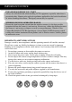
IMPORTANT NOTICE PLEASE READ BEFORE YOU START Always use with discretion when installing CCTV equipment, especially when there is perceived policy. Enquire relevant local regulations applicable to the lawful installation of video recording/surveillance. Third party consent may be required. WIRELESS DEVICES OPERATING RANGE Ensure the signal reception viewed from the wireless camera(s) is the best possible reception between the camera(s) and receiver.
FCC Compliance Statement: This device complies with Part 15 of the FCC rules. Operation is subjected to the following two conditions: (1) this device may not cause harmful interference, and (2) this device must accept any interference received, including interference that may cause undesired operation. Products with CE Marking comply with EMC Directive (2004/108/EC); Low Voltage Directive (73/23/EEC); R&TTE(1999/5/EC); ROHS Directive (2011/65/EU) issued by the Commission of the European Community.
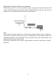
System “Device ID” and “Password” are provided on a label applied at the back of the LCD Monitor (behind the pull out stand). The “Device ID” and “Password” are needed for remote viewing. For security purpose, it is recommenced for user to copy the “Device ID” and “Password” information to the user manual, following by removing the label containing the “Device ID” and “Password” information. Please keep the device ID and password information in a safe place for future reference.
KIT CONTENT A Wireless Camera w/ stand x1 C Camera Antenna x 1 E Internet Cable x 1 G Instruction Manual x 1 B Wireless Touch Screen LCD Monitor x 1 D 5V/1A Power Adapter x2 F Screw Bag x 1 Tools Required: Electric drill 5mm masonry drill bit 15mm masonry drill bit No.
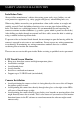
SAFETY AND INSTALLATION TIPS Installation Notes Always follow manufacturer’s advice when using power tools, steps, ladders, etc and wear protective equipment (e.g, safety goggles and gloves) when drilling holes, etc. When using ladders ensure they are positioned on a firm stable surface at an angle and suitably secured. Check for hidden electricity wires or water pipes before drilling any holes. If in doubt use a cable/pipe locator.
NOTE: The camera has an open field RF operating range of up to 150m. Secure camera stand on the stable surface Loosen up the Thumb screw Adjust proper view angle then secure the joint with thumb screw. Setting the Camera Channel (optional) The wireless camera is supplied preset to channel 1. The monitor supports up to 4 cameras. Follow the steps below in Camera Setup section to setup or change the monitor channel of the camera.
Pairing the Camera to Receiver (optional) Follow the steps in Camera Setup section to setup or change the channel of the camera. If you are adding another camera to link with the supplied monitor in this kit, then ensure its channel is set to a different channel to the existing camera(s). Note: If the camera is located within 1m to 1.5m from the monitor and the camera's volume on the receiver is turned on, then you may hear a whistling noise on the monitor which is the feedback picked up by the microphone.
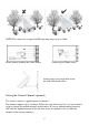
GETTING TO KNOW THE MONITOR AND CAMERA Receiver (Front view) Receiver (Back view) Antenna Power On/Off Pull-Out Stand SD slot Reset Button AC Power Connection Ethernet Jack WHAT THE LIGHTS MEAN Light Power status Link status State What it means On (Red) The camera is on. Off The camera is off. Flashing The camera is in pairing mode. On (Green) The camera is connected to the receiver. Off The camera is in standby.
Set up the Monitor 1. Flip out the stand, extend the antenna, connect AC/DC adapter to the power input on the side of the monitor. Then connect the other end of the adapter to the nearest power outlet. Press and hold the POWER button on the top of the monitor for 3 – 4 seconds to power it up. 2. 3. The receiver displays Welcome Screen for a few seconds and then transitions to the LIVE view. Place the SD card into the SD card slot located on the side of the monitor.
SYSTEM INTRODUCTION Your monitor’s system software operates through a series of screens that let you choose groups of operations. For example, when you tap on the camera icon in the Pop-up menu, you can set how you want the main viewing screen, “the Live screen” to display images from the paired cameras. You can scan between cameras, show all cameras on a single screen (Quad view), or only display specific camera. The Live screen lets you view the camera transmissions.
ICON WHAT THE ICON MEANS Camera Mode Select how you want the Live screen to display camera input: Scan between cameras (5 seconds) Quad view (all paired cameras display) Full view (1 camera displays on full screen) Volume Adjust the volume level. System Settings Access the system software operation and setting page or view recorded events. SD Capacity Indicates memory capacity remaining. Battery Capacity Displays battery capacity. This graphic shows battery at nearly full.
Live Screen Displays The Live screen displays in 2 views - Quad View or Full View. Quad View displays the images in 4 quadrants (only display camera that is ON). Tap a quadrant to display single camera view / full view. Tap on that image again to return to Quad View. Zoom Feature To zoom into a particular area, 1. Go to full view, then tap to activate zoom mode. 2. Select the zone by tapping the zone area to view zoom in screen. Recording Live Video 1. On the Live screen, tap 2.
Playing Back Recorded Video From the pop-up menu, tap the following icons The Record List screen displays: 1. 2. 3. 4. Tap on the highlighted day containing the recording you want to view. The Record List screen will display that day’s recordings listed in a folder. If you tap on a day that is not highlighted, a folder displays with no recordings listed. Tap on the recording you want to view. It displays on the screen.
SYSTEM MENU From the pop-up menu, tap the following icons The Main Screen displays: The SYSTEM MENU highlights the Camera Setup option as the default. Main Screen Camera Setup Recorder Setup Network Setup Alarm Setup System Setup Quick Tips Sub Screens Camera Setup Camera on Brightness Motion Detection What it Does Pairs new cameras to the receiver. Makes the cameras visible to the monitor. Brightens or darkens the video of that camera. Records when something moves in front of the camera.
SYSTEM OPERATION Camera Setup Screen Tap on camera setup. This screen should display: Camera Pairing Your camera is paired to the monitor at the factory to channel 1. To add new camera(s) to your system, you have to pair it to the different channel(s). From the pop-up menu, tap the following icons The Main Screen displays: 1. Tap the camera image you want to pair. A processing icon displays for a 60 second countdown. 2.
An X indicates a camera is OFF, a check indicates ON. Tap on the camera to turn it ON or OFF. Brightness From the pop-up menu, tap the following icons The screen displays: Tap the camera to change brightness level. The default brightness is 0, and the range is from -2 through 2.
Motion Detection From the pop-up menu, tap the following icons The screen displays: Tap the camera’s to set the sensitivity to Off, Low or High. Default = low. The screen will return to the Motion Detection screen after 10 seconds or when you press the Back icon. Email Alert The system can notify you when it detects motion from any camera by sending you an email alert. The email alert contains information such as the time that motion was detected and by which camera.
1. 2. Tap Enable to activate Email Alert or Disable to deactivate it. Tap on the SMTP Server field. A keyboard screen displays. 3. Enter your outgoing e-mail SMTP server (example: johndoe@gmail.com). You can switch the keyboard from alphabetical characters to numbers/symbols and back again by tapping the field to the left of the space bar. Tap Return. The Email Alert screen displays again. Repeat the previous step for the Password field. Tap Return.
Schedule Record Up to 5 scheduled recording sessions available in a single day. You are limited to the size of the SD card for how long a total recording time you have. These recording sessions must begin and end within a single 24-hour period. They cannot cross into the next day. From the pop-up menu, tap the following icons 1. 2. 3. 4. 5. 6. 7. The Schedule Record screen displays: Tap the camera/channel number you want to record (1 - 4). Multiple cameras can be selected.
From the pop-up menu, tap the following icons The Network Setup screen displays: Internet Setup 1. Tap Internet Setup icon to display the Internet Setup screen. 2. Tap on your selection and fill in the fields requested. Tap OK. 3. Tap OK at the system reboot prompt. The Network Setup screen displays.
Security Code Set up your security code to limit who can have access to the system from a remote location. 1. Tap Security Code icon to display the Security Code screen. 2. 3. If you have previously entered a code, the screen will display your current code Tap on the change code field, a key board screen displays. 4. 5. Enter your security code. Tap OK. The system will return to Network Setup screen. Note: Security code must be entered to gain remote access.
Network Information 1. Tap the Network Information icon to display the Network Information screen. 2. Tap the BACK arrow to return to the previous screen. Note: The DID is a unique code specific to your monitor and is required to gain remote access to your cameras over the internet. The information in the DHCP setting is assigned to your monitor from your home router. Alarm Setup Screen From the Alarm Setup screen, you can: Set the length of time the alarm sounds Select a melody for the alarm.
Period This selection allows you to select the alarm/siren duration for Clock Alarm and Timer. 1. Tap Period. The Set Siren Duration screen displays. 2. 3. Select the alarm duration time required Tap the BACK arrow to return to the previous screen. Melody This selection allows you to select a melody for the siren. 1. Tap Melody. The Change Siren Melody screen displays. 2. Select the melody required 3. Tap the BACK arrow to return to the previous screen.
System Setup Screen Power Saving In Power Saving mode, the monitor will shut off LCD after idle for 2 minutes. Press Power button once to reactivate the monitor. If a motion detection event or scheduled recording begins, the LCD turns back on automatically. 1. Tap Power Saving Enable to activate power saving. Default is off. 2. 3. A check mark appears on your selection. Tap the BACK arrow to return to the previous screen.
2. 3. Tap your selection; a check mark displays. Tap the BACK arrow to return to the previous screen. Note: From the Live screen, tap the Power button once to unlock the screen and return to normal touch screen operation. Time The Time screen lets you set up clock alarms, set the system time, and set a timer. From the pop-up menu, tap the following icons The screen displays: Clock Alarm This feature operates as an independent alarm clock.
2. 3. 4. 5. Tap on an alarm button (total of 5 to select from). Tap on the hour/minutes block then UP/DOWN arrows to set the time. Tap on AM/PM to toggle between the two. Tap SAVE, then back. Time Setting This screen contains fields to set the Month, Day, Year, Hour, Minute and AM/PM. 1. 2. 3. 4. Tap to display the Time Setting screen. Tap on each field to set it. The UP/DOWN arrows shift to that field. Use UP/DOWN to set the field. Tap on the AM/PM block to switch between the two.
1. 2. 3. Tap to display the Time Zone screen. Use UP/DOWN arrows to change the time zone for your region. Tap SAVE to complete the settings. Storage Management The Storage Management screen lets you format the SD card or set up the SD card overwrite function. Format When using an SD card other than the provided one, it is highly recommended that you format the card using these procedures. Formatting any SD card deletes all files on that card.
Overwrite This feature will overwrite the oldest files when the capacity of SD card is full. Turning on this feature will enable the system to start overwriting the oldest 300Mb files when the available capacity is less than 100Mb. From the pop-up menu, tap the following icons The Format Storage screen displays: Tap on the Overwrite feature. The check mark indicates the feature is enabled. System Upgrade Please make sure your system firmware has been updated to the latest version.
From the pop-up menu, tap the following icons The screen displays: Press the Start button to upgrade the firmware. Language English is the default language. If you change the language, all system settings default to the original factory settings. You will have to reenter any specialized settings. From the pop-up menu, tap the following icons 1. 2. 3. 4. The screen displays: Select the language required. The Restore Default Settings screen displays. Tap OK to continue.
Quick Tips The Quick Tips screen provides additional details on important subjects of system operation. Tap on a subject to display the information. REMOTE ACCESS Overview The DWH Series Video Security System lets you view live video from your iPhone, iPad, or Android smartphone or tablet. Free apps are available through the iTunes App Store or the Android Market. Receiver Power Supply Adaptor Requirements for Remote View Supported Device - iPhone / iPad / iPod Touch w/ iOS 5.0.
Recommended minimum internet upload speed 512Kbps upload speed (or bandwidth) to achieve up to an average of 2FPS viewing speed. Average viewing speed will depend on other restrictions by your ISP (internet service provider). Connecting to the Internet When the system is connected to the internet, the live video will continue to display on the monitor, but monitor’s touch operation will become limited.
Connecting to the Intranet (Home Network) If you choose “Disconnect from Internet” option after you connect the Ethernet cable into the back of the monitor, you can still access your live video from smartphone(s) or tablet(s) as long as those devices are also connected to the same network as the monitor. For example, your smartphone is connected to your home network via WiFi, in this case, live video will still be displayed on the monitor as well as on the smartphone.
Note: When you type in the default password, the system will notify you to change it. Please follow the instruction of the Device Password section to change the default password into your personal security code. 4. Click SAVE to complete the camera settings. 5. Repeat step 1 to 5 to add more cameras. After you add the camera(s) to the system, the Main Screen displays and lists all the camera connections vertically.
Live View What it Does Tap to capture screen images. The snapshots will be saved into the camera roll of your mobile device. Tap to record and tap again to stop recording. Tap to return to the main page. If you want to take snapshots: From the main screen, tap the camera you want to view From the Live View, tap the following icon: If you want to view your snapshots: For iOS: You snapshots will be named with the time stamp and saved into the Camera Roll > snapshot folder on your mobile device.
If you want to record videos: From the main screen, tap the camera you want to view From the Live View, tap the following icon: If you want to playback your videos: From the main screen, tap the following icons The Event List screen displays: Select the time intervals of the recorded video you want to see. Then tap the video name once to playback the video clip. Setup the push notification: The DWH security system will notify you via text message whenever any recording event occurs. 1. 2.
TROUBLE SHOOTING TROUBLE No image Poor picture quality The motion sensor not working No recording happens although it has the schedule set. Unable to pair the camera to the receiver A white image appears at night SOLUTIONS Screen lock may be on. Tap the Power button to unlock the screen. Make sure the camera is power on. Make sure the monitor has enough charge / connect it to AC/DC adaptor.
PRODUCT SPECIFICATION Camera Maximum channels Communication Range LCD Monitor Resolution Camera Resolution Operating Temperature Operating Voltage Current Consumption Night Vision Dimension - Receiver 4 150 meters in open space 800 x 480 Single Camera: 480x272 / Multiple Camera: 320x240 -10゚C ~ 50゚C DC 5V / 1A 500mA (MAX) 800mA (MAX) 8 meters 151x74x49 mm 184x128x28 mm Recording Time for Memory Card (32GB max) SD Card Capacity Single Camera Multiple Cameras (Full Screen) (QUAD Mode) 1GB 200 Minutes 130