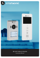
DIC-221 Intercom Series Instruction Manual
WARNING PRODUCT OVERVIEW 1. Please read these instructions carefully before installing and using the product. 2. Do not cut the power supply cable to extend it; the device (transformer) will not work with a longer cable. Do not plug in the device until all the wiring has been finished. INDOOR MONITOR 1 INSTALLATION SAFETY 1. Keep children and bystanders away while installing the products. Distractions can cause you to lose control. 2. Do not overreach when installing this product.
INSTALLATION - OUTDOOR UNIT INSTALLATION - INDOOR MONITOR When installing the outdoor unit, make sure that the location you wish to install it is dry. It is important that the camera or the electronics do not get wet. 1.Select a suitable location for installation. 1. Drill holes in the wall, insert the wall plugs in the holes. Place the bracket and tighten the screws. 2.Drill holes in the wall, insert the wall plugs in the holes. Place the bracket and tighten the screws. 3.
WIRING USE Intercom function: When in standby, when a visitor presses the call button on the outdoor unit, the indoor-monitor will chime and you will see a live view of the visitor on the screen. Press the intercom button to speak to the visitor. Monitor function: Press this button on the indoor-monitor unit to see a live view of the outdoor unit camera. Internal Intercom: When in standby, press and hold the intercom button to activate the internal intercom function.
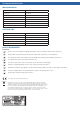
TECHNICAL SPECIFICATION INDOOR MONITOR Supply Voltage 15V 1A Screen size 3.5” inch Color configuration R.G.B.delta Video System PAL/NTSC Effective Pixels 320x240 Consumption current 300mA±10mA Operation temperature -10˚C - +50˚C Operation Humidity 85%(Max) OUTDOOR UNIT Imaging sensor type 1/4” CMOS View angle 70˚ Minimum illumination 0Lux Night vision distance 0.