SMC2586W-G
Copyright Information furnished by SMC Networks, Inc. (SMC) is believed to be accurate and reliable. However, no responsibility is assumed by SMC for its use, nor for any infringements of pat-ents or other rights of third parties which may result from its use. No license is granted by implication or otherwise under any patent or patent rights of SMC. SMC reserves the right to change specifications at any time without notice. Copyright © 2004 by SMC Networks, Inc.
Federal Communication Commission Interference Statement This equipment has been tested and found to comply with the limits for a Class B digital de-vice, pursuant to Part 15 of the FCC Rules. These limits are designed to provide reasonable protection against harmful interference in a residential installation. This equipment generates, uses and can radiated radio frequency energy and, if not installed and used in accordance with the instructions, may cause harmful interference to radio communications.
Cet appareil numerique respecte les limites de bruits radioelectriques applicables aux appa-reils umeriques de Classe B prescrites dans la norme sur le material brouilleur: “Appareils Numeriques,” NMB-003 edictee par l’Industrie. EC Conformance Declaration CE 0560 (!) SMC contact for these products in Europe is: SMC Networks Europe, Edificio Conata II, Calle Fructuós Gelabert 6-8, 2o, 4a, 08970 - Sant Joan Despí, Barcelona, Spain. This RF product complies with R&TTE Directive 99/5/EC.
10. Alle Hinweise und Warnungen, die sich am Gerät befinden, sind zu beachten. 11. Wird das Gerät über einen längeren Zeitraum nicht benutzt, sollten Sie es vom Stromnetz trennen. Somit wird im Falle einer Überspannung eine Beschädigung vermieden. 12. Durch die Lüftungsöffnungen dürfen niemals Gegenstände oder Flüssigkeiten in das Gerät gelangen. Dies könnte einen Brand bzw. elek trischen Schlag auslösen. 13. Öffnen sie niemals das Gerät.
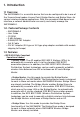
1. Introduction 1.1 Overview The SMC2586W-G is a versatile device that can be configured to be in one of the 3 opera-tional modes—Access Point, Bridge Master, and Bridge Slave—for various wireless bridging applications. With the convenient Web-based user interface, a network administrator can easily and clearly manage the SMC2586W-G. 1.2.
• 64-bit and 128-bit WEP (Wired Equivalent Privacy). For wireless data encryp-tion. • IEEE 802.1x/RADIUS. When the SMC2586W-G is in Access Point mode, it can be configured to authenticate wireless users and distribute encryption keys dynami-cally by IEEE 802.1x Port-Based Network Access Control and RADIUS (Remote Authentication Dial-In User Service). • WPA (Wi-Fi Protected Access). The SMC2586W-G supports the new WPA stan-dard. Both WPA-PSK (Pre-Shared Key) mode and full WPA mode are supported.
• Detachable antenna. The SMC2586W-G antenna can be replaced with SMC high-gain antennas for long operating range. • DHCP client. The SMC2586W-G can automatically obtain an IP address from a DHCP server. • DHCP server. The SMC2586W-G can automatically assign IP addresses to computers or other devices by DHCP (Dynamic Host Configuration Protocol). • Static DHCP mappings.
• UPnP. The SMC2586W-G responds to UPnP discovery messages so that a Win-dows XP user can locate the SMC2586W-G in My Network Places and use a Web browser to configure it. • Telnet. The SMC2586W-G can be managed by Telnet. • System log. For system operational status monitoring. • Local log. System events are logged to the on-board RAM of the SMC2586W-G and can be viewed using a Web browser. • Remote log by SNMP trap. Systems events are sent in the form of SNMP traps to a remote SNMP management server.
2. First-Time Installation and Configuration 2.1 Selecting a Power Supply Method The SMC2586W-G can be powered by either the supplied power adapter or the optional SMCPWR-INJ3 EliteConnect™ Power Injector. The SMC2586W-G automatically selects the suitable power depending on your decision. To power the SMC2586W-G by the supplied power adapter: 1. Plug the power adapter to an AC socket. 2. Plug the connector of the power adapter to the power jack of the SMC2586W-G.
Fig. 2. Connecting Ethernet cables to SMCPWR-INJ3. 5. Check the “ACTIVE” LED: if power is successfully fed into the SMC2586W-G, the “AC-TIVE” LED will be on (Red light); otherwise, the “ACTIVE” LED will be off. 6. If the electricity current is over the normal condition (Io°÷1.0 A), the “ACTIVE” LED will flash (Red light). NOTE: SMCPWR-INJ3 is specially designed for “SMC2586W-G EliteConnect™ 2.4GHz 11Mbps Wireless Bridge.
2.3 Preparing for Configuration To configure an SMC2586W-G, a managing computer with a Web browser is needed. For first-time configuration of an SMC2586W-G, an Ethernet network interface card (NIC) should have been installed in the managing computer. For maintenance-configuration of a deployed SMC2586W-G, either a wireless computer or a wired computer can be employed as the managing computer. NOTE: If you are using the browser, Opera, to configure an SMC2586W-G, click the menu item File, click Preferences..
Changing the TCP/IP Settings of the Managing Computer Use the Windows Network Control Panel Applet to change the TCP/IP settings of the managing computer, so that the IP address of the computer and the IP address of the SMC2586W-G are in the same IP subnet. Set the IP address of the computer to 192.168.2.xxx (the default IP address of the SMC2586W-G is 192.168.2.50) and the subnet mask to 255.255.255.0.) [DHCP Client is enabled by default. It will default to 192.168.2.
NOTE: It is strongly recommended that the password be changed to other value for security reasons. On the start page, click the General, Password link to change the value of the password (see Section 3.3.1 for more information). TIP: Since the Status page shows the current settings and status of the SMC2586W-G, it can be saved or printed within the Web browser for future reference. Fig. 6. The Status page. Step 1: Selecting an Operational Mode Fig. 7. Operational modes settings.
The SMC2586W-G supports 3 operational modes for meeting various wireless connectivity requirements: • Access Point (AP). The AP mode enables IEEE 802.11 Stations (STAs) to auto-matically associate with it via the standard IEEE 802.11 association process. In addition, the IEEE 802.11 WDS (Wireless Distribution System) technology can be used to manually establish wireless links between two APs or between an AP and a Bridge Master. • Bridge Master (BM).
The relationships among the operational modes and the wireless link types are shown in the following table: Table 1. Operational modes vs. wireless link types. From the table, a WDS link can be establish between two APs, a BM-BS link can be estab-lished between a Bridge Master and a Bridge Slave, but no wireless link can be established between a Bridge Slave and an AP. Select an operational mode and click Save at the bottom of this page, and then you are brought back to the start page.
Step 3: Configuring IEEE 802.11 Settings Fig. 9. IEEE 802.11g communication settings. Go to the IEEE 802.11, Communication section to configure IEEE 802.11grelated commu-nication settings, including Channel number and Network name (SSID). The number of available RF channels depends on local regulations. NOTE: The Regulatory domain setting of the SMC2586W-G sold in the U.S. and Canada in not configurable. It’s set to FCC by default. As a result, only channels from 1 to 11 are available.
To enable a WDS link: 1. Specify the MAC address of the AP or bridge at the other end of the WDS link. 2. Select the corresponding Enabled check box. For example, assume you want two SMC2586W-Gs with MAC addresses 00-02-65-01-62-C5 and 00-02-65-01-62-C6 to establish a WDS link between them. On SMC2586W-G 00-02-65-01-62-C5, set the peer MAC address of port 1 to 00-02-65-01-62-C6 and on SMC2586W-G 00-02-6501-62-C6, set the peer MAC address of port 1 to 00-02-65-01-C5. 3.
Step 4: Reviewing and Applying Settings Fig. 13. Settings changes are highlighted in red. On the start page, you can review all the settings you have made. Changes are highlighted in red. If they are OK, click Restart for the new settings to take effect. NOTE: It takes about 7 seconds for the SMC2586W-G to complete its restart process. NOTE: If you decide not to change settings of the SMC2586W-G, be sure to log off by clicking the Log Off button on the left menu.
2.5 Deploying the SMC2586W-G After the settings have been configured, deploy the SMC2586W-G to the field application environment. Connect the SMC2586W-G to an Ethernet LAN through an Ethernet switch/hub. If external high-gain directional antennas are needed, it may be difficult to align the antennas. Here are some suggestions for antenna alignment. To adjust the alignments of a pair of SMC high-gain antennas: 1. Connect each SMC2586W-G to a computer via Ethernet. 2.
3. Using Web-Based Management ADD SIGNAL STRENGH AND LINK QUALITY FEATURE IN SLAVE BRIDGE MODE IN THIS CHAPTER 3.1 Overview Fig.15 The Start page. Menu Structure The left side of the start page contains a menu for you to carry out commands. Here is a brief description of the hyperlinks on the menu: • Home. For going back to the start page. • Status. Status information. • Wireless Clients. The status of the wireless clients (STAs and Bridge Slaves) currently associated with the SMC2586W-G. • DHCP Mappings.
backing up and restoring configuration, and configuration reset of the SMC2586W-G. • TCP/IP. TCP/IP-related settings. • Addressing. IP address settings for the SMC2586W-G to work with TCP/IP. • DHCP Server. Settings for the DHCP (Dynamic Host Configuration Protocol) server on the SMC2586W-G. • IEEE 802.11. IEEE 802.11g-related settings. • Communication. Basic settings for the IEEE 802.11g interface of the SMC2586W-G to work properly with wireless clients. • Security.
If you click Save, the start page will reflect the fact that the configuration settings have been changed by showing two buttons—Restart and Cancel. In addition, changes are highlighted in red. Clicking Cancel discards all the changes. Clicking Restart restarts the SMC2586W-G for the new settings to take effect. Fig. 18 Settings have been changed. Home and Refresh Commands Fig. 19 Home and Refresh. At the bottom of each status page shows read-only information and two buttons— Home and Refresh.
On this page, the status information of each associated client (STA or Bridge Slave), includ-ing its MAC address, IP address, user name, number of bytes it has send, number of bytes it has received, and the time of its last activity, is shown. Current DHCP Mappings Fig. 21 Current DHCP mappings. On this page, all the current static or dynamic DHCP mappings are shown.
System events are recorded in the memory of the SMC2586W-G. The logged information is useful for troubleshooting purposes. The system events are divided into several categories, and you can select which categories of events to log. See Section 3.6.2.3 for more informa-tion. 3.3 General Operations Selecting an Operational Mode Fig. 23. Operational modes settings. The SMC2586W-G supports 3 operational modes for meeting various wireless connectivity requirements: • Access Point (AP).
• Bridge Slave (BS). Use this mode to provide the Bridge Slave functionality of the SMC2682W. The Bridge Slave mode is designed to work in those networks where SMC2682W Wireless Bridge Masters are already installed. In any mode, the SMC2586W-G forwards packets between its Ethernet interface and wire-less interface for wired hosts on the Ethernet side and wireless host(s) on the wireless side. There are 3 types of wireless links between two SMC2586W-Gs or between an SMC2586W-G and another wireless device.
From the table, a WDS link can be establish between two APs, a BM-BS link can be estab-lished between a Bridge Master and a Bridge Slave, but no wireless link can be established between a Bridge Slave and an AP. Fig. 24 Connectivity Limitation. In Fig. 24 packets from STA cannot reach X, and vice versa. Changing Password Fig. 25 Password. On this page, you can change the user name and password for the rights to modify the con-figuration of the SMC2586W-G.
browser types and versions, HTTP-based firmware management operations may not work properly with some Web browsers. If you cannot successfully perform HTTP-based firmware management operations with your Web browser, try the TFTP-based method. Upgrading Firmware by HTTP Fig. 27 Firmware upgrade by HTTP. To upgrade firmware of the SMC2586W-G by HTTP: 1. Click Browse and then select a correct firmware .bin file. The firmware file path will be shown in the Firmware file name text box. 2.
To restore configuration of the SMC2586W-G by HTTP: 1. Click Browse and then select a correct configuration .hex file. You have to make sure the file name is the SMC2586W-G_Backup.hex. The file path will be shown in the Con-figuration file name text box. 2. Click Restore to upload the configuration file to the SMC2586W-G. Upgrading Firmware by TFTP Fig. 30 TFTP server settings.
6. Choose TFTP as the Firmware management protocol. 7. Specify the IP address of the computer, which acts as a TFTP server. If you don’t know the IP address of the computer, open a Command Prompt from the computer running the TFP server, and type IpConfig, then press the Enter key. 8. Trigger the firmware upgrade process by clicking Upgrade. Fig. 32 TFTP Server. NOTE: After the dialog box of the TFTP server program appears, be sure to specify the folder that the downloaded firmware files reside.
Backing up and Restoring Configuration Settings by TFTP Fig. 33. Configuration backup/restore. To back up configuration of the SMC2586W-G by TFTP: 1. Use a computer that will serve as a TFTP server and as a managing computer to trigger the backup process. 2. Connect the computer and one of the LAN Ethernet switch port with a standard Ethernet cable. 3. Configure the IP address of the computer so that the computer and the SMC2586W-G are in the same IP subnet. 4. Run the TFTP Server utility on the computer.
the configura-tion backup file resides. A configuration backup file is named SMC2586W-G_Backup.hex. 5. On the computer, run a Web browser and click the General, Firmware Tools hyperlink. 6. Choose TFTP as the Firmware management protocol. 7. Within the Configuration Backup/Restore section, specify the IP address of the com-puter, which acts as a TFTP server.
The IP address of the SMC2586W-G can be manually set (Set Manually) or automatically assigned by a DHCP server on the LAN (Obtain from a DHCP Server – enabled by de-fault). If you are manually setting the IP address, Subnet mask, and Default gateway settings, set them appropriately, so that they comply with your LAN environment. In addition, you can specify the Host name and Domain (DNS suffix) of the SMC2586W-G. DHCP Server Fig. 36 Basic DHCP server settings.
DHCP Mappings Fig. 37 Static DHCP mappings. IP addresses of servers are often static so that clients could always locate the servers by the static IP addresses. By using Static DHCP Mappings, you can ensure that a host will get the same IP address when it requests one from the DHCP server. Therefore, instead of configuring the IP address of an intranet server manually, you can configure the server to obtain an IP address by DHCP and it is always assigned the same IP address.
For specific needs such as configuring the SMC2586W-G as a wireless LANto-LAN bridge, the AP functionality can be disabled, so that no wireless client can associate with the SMC2586W-G. (This will only work while the SMC2586W-G bridges are configured in AP/WDS mode, if you are using Master/Slave mode and disable the AP functionality on the Master no wireless clients or bridge slaves will be able to connect.) Since the IEEE 802.11g-based SMC2586W-G is also IEEE 802.
Wireless Distribution System Fig. 40 Wireless Distribution System. Traditionally, access points are connected by Ethernet. By IEEE 802.11 Wireless Distribution System (WDS), APs can communicate with one another wirelessly. For example, in Fig. 40, AP 2 acts as an access point for the notebook computers and it forwards packets sent from the notebook computers to AP 1 through WDS. Then, AP 1 forwards the packets to the Ethernet LAN.
Fig. 42 Wireless Distribution System settings. To enable a WDS link: 3. Specify the MAC address of the AP or bridge at the other end of the WDS link. 4. Select the corresponding Enabled check box. For example, assume you want two SMC2586W-Gs with MAC addresses 0002-65-01-62-C5 and 00-02-65-01-62-C6 to establish a WDS link between them.
WARNING: Do not let your network topology consist of wireless bridges, Ethernet switches, Ethernet links, and WDS links that form a loop. If there are any loops that exist, packets will circle around the loops and network performance will be seriously degraded. Fig. 44 Network topology containing a loop. Security IEEE 802.11b/g security settings include SSID broadcasts, Security mode, IEEE 802.11 Authentication algorithm, WEP keys, MAC-Address-Based Access Control. Basic Fig. 45 Basic IEEE 802.
Wireless Client Isolation is a feature for the SMC2586W-G in AP or Bridge Master mode to block wireless-to-wireless traffic between STAs so that the STAs cannot see each other. This feature is useful for WLANs deployed in public places. This way, hackers have no chance to attack other wireless users in a hotspot.
As illustrated in Fig. 46 when AP 1 and AP 2 are using the “This AP Only” option, AP1 blocks wireless traffic between STA 1 and STA 2, while wireless traffic between STA 2 and STA 3, which are associated with different APs, is still allowed. If the “All APs in This Subnet” option is used as shown in Fig. 47, AP 1 and AP 2 communicates with each other via an inter-AP protocol to share their STA association information to block wireless traffic among all the STAs.
with various WLAN network adapters. There are three options available, including Open System, Shared Key, and Auto. When WEP is enabled by a security mode, the Key length can be specified to be 64 Bits or 128 Bits. The Selected key setting specifies the key to be used as a send-key for encrypt-ing traffic from the local device side to the remote device side. All 4 WEP keys are used as receive-keys to decrypt traffic from the remote device side to the local device side.
2. Set the Access control type to inclusive. 3. Specify the MAC address of a wireless client to allow access, and then click Add. 4. Repeat Step 3 for each other wireless client. To delete an entry in the access control table: • Click Delete next to the entry. NOTE: The size of the access control table is 64. Fig. 49 MAC ACL download settings.
IEEE 802.1x/RADIUS IEEE 802.1x Port-Based Network Access Control is a new standard for solving some secu-rity issues associated with IEEE 802.11, such as lack of user-based authentication and dy-namic encryption key distribution. With IEEE 802.1x, a RADIUS (Remote Authentication Dial-In User Service) server, and a user account database, an enterprise or ISP (Internet Service Provider) can manage its mobile users’ access to its wireless LANs. Before granting access to a wireless LAN supporting IEEE 802.
SMC2586W-G supports IEEE 802.1x and can be configured to communicate with two RADIUS servers. When the primary RADIUS server fails to respond, SMC2586W-G will try to communicate with the secondary RADIUS server. You can specify the length of timeout and the number of retries before communicating with the secondary RADIUS server after failing to communicate with the primary RADIUS server. An IEEE 802.
Ethernet Type Filters Fig. 53 Ethernet type filters settings. The Ethernet type filed of the MAC (Media Access Control) header of a packet incoming from the WLAN or Ethernet interface is inspected for filtering. In a rule, specify the hex-decimal Ethernet type number and give the rule a name. IP Protocol Filters Fig. 54 IP protocol filters settings. The protocol, source address, and destination address fields of a packet incoming from the WLAN or Ethernet interface is inspected for filtering.
TCP/UDP Port Filters Fig. 55 TCP/UDP port filters settings. The destination port field the TCP or UDP header of a packet incoming from the WLAN or Ethernet interface is inspected for filtering. In a rule, specify the decimal Destination Port, Protocol type (TCP/UDP), and the name of the higher-level protocol (Application Name). Management Fig. 56 Basic management settings. The SMC2586W-G can be managed by Telnet. This functionality can be either enabled or disabled.
NOTE: Make sure you have installed the necessary Windows UPnP components on your Windows XP computer. System Log Fig. 58 System log settings. System events can be logged to the on-board RAM of the SMC2586W-G (Local log) or sent in the form of SNMP trap (Remote log by SNMP trap) or BSD Syslog (Remote log by BSD Syslog) to a remote SNMP trap monitoring server or remote Syslog server, respectively. See the next subsection for more information about SNMP trap settings.
SNMP Fig. 59 SNMP settings. The SNMP (Simple Network Management Protocol) functionality can be disabled, and you can specify the name (used as a password) of the read-only and read-write community. In addition, up to 5 SNMP trap targets can be set in the SNMP Trap Table. To specify a trap target: 1. Type the IP address of the target host. 2. Type the Community for the host. 3. Select the corresponding check box next to the IP address text box. 4.
4. EliteConnect Management Utility 4.1. Introduction This chapter gives introductory information, such as the design goal and features, on SMC EliteConnect™ Management Utility. In Chapter 4.2, it outlines EliteConnect Management Utility’s basic functionality by using a sample device list file, which is installed by the setup package of EliteConnect Management Utility. EliteConnect Management Utility is designed to manage SMC2582W-B EliteConnect 802.11b Wireless Bridge and SMC2586W-G EliteConnect 802.
• DNS domain name. DNS (Domain Name System) domain name of the device. These information items serve as memos for the network administrator and they are optional. And the following information items must be specified so that EliteConnect Management Utility can communicate with the device by HTTP (HyperText Transfer Protocol): • IP address. IP address of the device. • HTTP port. HTTP port through which the device accepts HTTP traffic.
• Configuring by Web browser. Launching the default Web browser to manage the selected device. • Batch processing. Applying a network management command to multiple devices at a time. The following commands are supported: • Check Alive. Checking whether the selected devices are operating. • Change SSID. Changing the SSID setting of every selected device. • Upgrade Firmware by TFTP and HTTP. Upgrading device firmware. • Back up Configuration by TFTP and HTTP.
Overview User Interface Fig. 60 Main user interface. The main user interface of EliteConnect Management Utility is three-paned. The upper right pane is the Device List View, which shows the devices to manage. The upper left pane is the Workspace Window, which enables you to filter the active device list or switch to another device list. The bottom pane is the History Log View.
Connecting the Managing PC and a Managed Device You need at least one SMC2582W-B EliteConnect 802.11b Wireless Bridge or SMC2586W-G EliteConnect 802.11g Wireless Bridge to follow the remainder of the tutorial. Connect the PC on which EliteConnect Management Utility will run and the device with Ethernet. And then, configure the IP address of the PC and of the device so that they are in the same IP subnet. Running SMC EliteConnect™ Management Utility Fig.
Fig. 62 Device Properties dialog box. On the left side of the title bar of the Device Properties dialog box is a “Pin” button. Click this button to pin the dialog box (the icon will be changed to ) so that it will always stay on top of other windows. Otherwise, the Device Properties dialog box disappears if you click anywhere outside of the dialog box. Clicking New Device adds a new item to the device list. You can repeat this procedure sev-eral times to add more items to the device list.
Editing the Device List Fig. 63 Edit menu. Select the desired device item from the device list. You can select consecutive device items by clicking while holding the Shift key. And you can select inconsecutive device items by clicking while holding the Ctrl key. The Select All command on the Edit menu enables you to select all devices in the device list. Selected device items can be deleted, cut or copied to the Clipboard. Device items cut or copied to the Clipboard can be pasted back to the device list.
of EliteConnect Man-agement Utility and an empty new device list file have been opened. Filtering the Device List Fig. 65 Filter View of the Workspace window. You can filter a device list by clicking a tree item on the Filter tab of the Workspace window. The tree hierarchy represents filtering criteria. Clicking the “All” tree item (level 0—no filtering) shows all devices in the device list. A level-1 tree item represents filtering by Project.
Fig. 6. Sorting by IP address, in descending order. NOTE: If a newly opened device list file is sorted, an asterisk mark “*” will be added to the file name shown in the title bar of EliteConnect Management Utility, which means the contents of the device list file have been modified. Rearranging the Column Order Fig. 68 Rearranging the column order by a drag-and-drop operation. The column order can be rearranged by drag-and-drop operations. Just drag a column header and drop it to another position.
Any device list columns can be hidden by clearing corresponding check boxes next to the menu items of the Columns sub-menu of the View menu. Clicking an unchecked menu item shows its corresponding device list column, and the menu item becomes checked next time you open the Columns sub-menu. Managing Devices After selecting one or more devices in the device list, you can carry out the device manage-ment commands on the Device menu to manage the selected device(s).
Fig. 72 History Log View. Configuring a Device by Web Browser Select the device item in the device list, which represents the SMC2582W-B or SMC2586W-G you use for this tutorial, and then carry out the Configure by Web Browser command on the Device menu. The default Web browser will be launched for you to manage the device. 4.3 Using SMC EliteConnect™ Management Utility This chapter provides more detailed explanations of the EliteConnect Management Utility functionalities.
The main user interface of EliteConnect Management Utility consists of three-paned. The upper right pane is the Device List View, which shows the devices to manage. The upper left pane is the Workspace Window, which enables you to filter the active device list or switch to another device list. The bottom pane is the History Log View. In addition, EliteConnect Management Utility is equipped with a menu bar and two toolbars for functions such as device list editing and device management.
Filter View Fig. 75 Filter View. EliteConnect Management Utility analyses the structure of the devices items in the active device list and shows the results in a tree fashion on the Filter tab of the Workspace win-dow. The active device list can be filtered by clicking a tree item (see Section 4.3.3.6 for more information).
File View Fig. 76 File View. The File tab of the Workspace window lists all opened device list files so that you to quickly switch between them (see Section 4.3.3.8 for more information). History Log View Fig. 77 History Log View. The History Log View shows progress and results of network management commands. The contents of the History Log View can also be saved to a log file for later reference (see Sec-tion 4.3.2.4.2 for more information).
• Close. Close the active document. • Save. Save the active document. • Save As. Save the active document with a new name. • Print. Print the active document. • Print Preview. Display full pages. • Print Setup. Change the printer and printing options. • Send. Send the active document through electronic mail. • Shortcuts to up to 4 MRU (Most Recently Used) files. • Exit. Quit the application; prompts to save documents. • Edit • Undo. Undo the last action. • Redo. Redo the previously undone action. • Cut.
• Configure by Web Browser. Launch the default Web browser to configure the first selected device. • Change SSID. Change the SSID setting of selected device. • Change Password. Change the password setting of selected device. • Upgrade Firmware by TFTP. Upgrade the firmware of selected device by TFTP. • Back up Configuration by TFTP. Back up the configuration of selected device to a file by TFTP. • Restore Configuration by TFTP. Restore the configuration of selected device from a file by TFTP.
Shortcut Menu Fig. 78 Shortcut menu Right clicking anywhere within the Device List View brings up a shortcut menu as shown in Fig. 78 The commands on the shortcut menu are shortcuts to some of the main menu commands. • Cut—Cut command on the Edit menu • Copy—Copy command on the Edit menu. • Paste—Paste command on the Edit menu. • Delete—Delete command on the Edit menu. • Select All—Select All command on the Edit menu. • Add New Device—New Device command on the Insert menu.
command on the Device menu. • Restore Configuration by HTTP—Restore Configuration by HTTP command on the Device menu. • Properties—Properties command on the View menu. Toolbars Toolbar commands are shortcuts to some of the main menu commands. There are two tool-bars—Basic and Device. Fig. 79 Basic toolbar. The commands in the Basic toolbar (from left to right) are listed as follows: • New on the File menu. • Open on the File menu. • Save on the File menu. • Cut on the Edit menu. • Copy on the Edit menu.
• Check Alive on the Device menu. • Configure by Web Browser on the Device menu. • Change Password on the Device menu. • Change SSID on the Device menu. • Change RADIUS Servers on the Device menu. • Upgrade Firmware by TFTP on the Device menu. • Back up Configuration by TFTP on the Device menu. • Restore Configuration by TFTP on the Device menu. • Upgrade Firmware by HTTP on the Device menu. • Back up Configuration by HTTP on the Device menu. • Restore Configuration by HTTP on the Device menu.
Fig. 81 Floating Workspace window. Fig. 82 History Log View docked to the right side.
Rearranging the Column Order of the Device List View Fig. 83 Rearranging the column order by a drag-and-drop operation. The column order can be rearranged by drag-and-drop operations. Just drag a column header and drop it to another position. For example, as shown in Fig. 83, the Zone 1 column will be inserted between the Status and the Project columns after the drag-and-drop operation is completed. Showing or Hiding the Columns of the Device List View Fig. 84 Showing or hiding some device list columns.
General Options Fig. 85 General tab. On this tab, you can specify the action taken when a device item in the active device list is double-clicked, the number of simultaneous device management commands, and whether the Device Password List function will be enabled. There are two options for the action taken when a device item is doubleclicked—Launches the default Web browser to configure the device or Shows the device’s properties (default).
Fig. 86 A sample Device Password List. Select the Use the following Device Password List instead of asking for device user name and password check box, and specify the location of the device password list file by clicking the “…” button. Logging Options Fig. 87 Logging tab. On this tab, you can specify whether the contents of the History Log View are also saved to a log file.
server for device firmware upgrade. EliteConnect Management Utility supports a “pull” style and a “push” style of device firmware upgrade. The pull style is achieved by HTTP and TFTP, while the push style is solely achieved by HTTP. The pull style works like the following: 1. EliteConnect Management Utility issues an HTTP command to the device to trigger the firmware upgrade process. 2.
HTTP Options Fig. 89 HTTP tab. On this tab, you can configure behavior parameters of EliteConnect Management Utility’s Web client engine—Microsoft Internet Explorer control. You may refer to Microsoft documentation about how to pick good values for Connect retries, Connect timeout, Receive timeout, and Send timeout. Experiments are helpful in determining values for these parameters. Clicking Reset to Defaults resets the settings on this tab to default values.
Fig. 90 Device Properties dialog box. To add a new device item to the active device list, click New Device on the Insert menu. And then a new device item is added to the device list and the Device Properties dialog box ap-pears for you to enter device properties. The Deployment and Identification groups of properties and the Comments property are optional for annotation purposes.
Click a device item to select it. A selected device item is highlighted. Multiple Consecutive Selections Fig. 92 Multiple consecutive selections. To select a block of consecutive device items: 1. Click the first item of the block. 2. Click the last item of the block while holding the Shift key. Multiple Inconsecutive Selections Fig. 93 Multiple inconsecutive selections. To select several inconsecutive device items: 1. Click the first item. 2. Click other items while holding the Ctrl key.
more information). Editing the Device List Fig. 94 Edit menu. You can use the commands on the Edit menu to edit the active device list. Refer to Section 4.3.1.5 for explanations of the commands. Filter the Device List Fig. 95 Device list filtering. You can filter a device list by clicking a tree item on the Filter tab of the Workspace window. The tree hierarchy represents filtering criteria. Clicking the “All” tree item (level 0—no filtering) shows all devices in the device list.
Device List View. For example, if you click the IP Address header, the device list will be sorted in ascending order by IP address, as shown by Fig. 96 Fig. 96 Sorting by IP address, in ascending order. Clicking the IP Address header one more time sorts the device list in descending order, as shown by Fig. 97. Fig. 9. Sorting by IP address, in descending order.
Viewing All Opened Device List Files Fig. 98 Viewing all opened device list files. You can switch between all opened device list files by clicking the corresponding tree items on the File tab of the Workspace window. Arranging Device List Windows The commands on the Window menu enable you to arrange your Device List View window and switch between them. Fig. 99 Window menu. Cascading Windows Fig. 100 Cascaded device list windows.
windows so that they overlap. Tiling Windows Fig. 101 Tiled windows. The Tile command on the Window menu arranges the Device List View windows as non-overlapping tiles. Arranging Minimized Windows Fig. 102. Minimized windows put in order. The Arrange Icons command on the Window menu arranges minimized Device List View windows so that they stay at the bottom.
5. Monitor the progress of the command in the History Log View. 6. See the results of the command in the History Log View and in the Status column of the Device List View. NOTE: You have to make sure a device is reachable by EliteConnect Management Utility through the IP address/domain name and port specified in the device list. Canceling Batch Command Execution Fig. 104 Cancel Waiting Commands menu command.
Changing the SSID Setting of Devices To change the SSID setting of selected device, carry out the Change SSID command. You’ll be prompted to specify the new SSID. Fig. 105 Changing SSID dialog box. Changing the Administration User Name and Password of Devices To change the administration user name and password settings of every selected device, carry out the Change Password command.
SMC2586W-G don’t support multiple administration user name/password pairs.) If the Device Password List functionality is disabled, Current admin. user name and Current admin. password, New user name will not be shown in the Changing User Name and Password dialog box. Fig. 107 Changing User Name and Password dialog box if using a Device Password List. Changing the RADIUS Server Setting of Devices To change the RADIUS server settings of every selected device, carry out the Change RADIUS Servers command.
Restoring Device Configuration Carry out the Restore Configuration by TFTP command. Managing Device Firmware by HTTP To manipulate firmware and configuration files of every selected device by HTTP, carry out the various By-HTTP commands. You’ll be prompted to specify the folder containing or to contain the files. Refer to Section 4.3.2.4.3 for more information. Upgrading Device Firmware Carry out the Upgrade Firmware by HTTP command.
Printing the Active Device List To print the active device list, carry out the Print command on the File menu. And you can preview the pages that will be printed by carrying out the Print Preview command.
Sending the Active Device List to Others by E-mail The active device list can be sent to others by e-mail. Click Send on the File menu to do this. Appendix A: Default Settings TIP: Press the Default button on the powered-on SMC2586W-G to reset the configuration settings to factory-default values. Appendix B: Troubleshooting Check the following first: • Make sure that the power of the SMC2586W-G is on and the Ethernet cables are con-nected firmly to the RJ-45 jacks of the SMC2586W-G.
• Make appropriate WEP settings of the client computer to match those of the SMC2586W-G. • Is the prospective SMC2586W-G within range of wireless communication? • Check the signal strength and link quality sensed by the WLAN NIC. TCP/IP Settings Problems Fig. 110. Communication stages for a client to reach its correspondent host. For a wireless client computer to communicate with a correspondent host on the Internet by the host’s domain name (e.g. http://www.wi-fi.
the IP ad-dress of the SMC2586W-G are in the same IP subnet. TIP: If you forget the current IP address of the SMC2586W-G, use Wireless Router/AP Browser to get the information (see Appendix B-3).use the SMC Scan utility that is on the CD. • The DNS server(s) of the client computer do not respond to ping from the client computer. • Solve the preceding problems first.
power connector from the power jack, and then re-plug the connector to restart the SMC2586W-G. • Contact our technical support representatives to report this problem, If this happens after a failed firmware upgrade process, the firmware of the SMC2586W-G may have been corrupted. • If the SMC2586W-G still does not work after restarting, there may be hardware component failures in the SMC2586W-G. • Contact our technical support representatives for repair.
this and every product we sell with a 30 day satisfaction guarantee and with a limited-lifetime warranty. Standards: • 802.11b • 802.11g • 802.3 • 802.3u • 802.3af SMC2682W are in the Bridging environment) • Bridge Slave (used when SMC2586W-G, SMC2582W-B, and SMC2682W are in the Bridging environment) Data rate & modulation: • OFDM@54Mbps, CCK@11/5.5Mbps, DQPSK@2Mbps and DBSK@1Mbps Interface: • 10/100 Mbps RJ-45 Connector • RS-232c Serial Connector • 802.
Power Supply: • Input: 100VAC 60Hz • Output: 12VDC, 1A Dimensions (without antenna): • 8.5” x 5.5 “ x 1.25” Weight: • 0.96 lbs 802.
FOR TECHNICAL SUPPORT, CALL: From U.S.A. and Canada (24 hours a day, 7 days a week) (800) SMC-4-YOU; Phn: (949) 679-8000; Fax: (949) 679-1481 From Europe : Contact details can be found on www.smc-europe.com or www.smc.com INTERNET E-mail addresses: techsupport@smc.com european.techsupport@smc-europe.com Driver updates: http://www.smc.com/index.cfm?action=tech_support_drivers_downloads World Wide Web: http://www.smc.com/ http://www.smc-europe.com/ For Literature or Advertising Response, Call: U.S.A.