EZ Card ISA Cover 3/31/98 5:49 PM Page 2 EZ Card 10 10 Mbps Ethernet ISA Network Cards ◆ ◆ ◆ ◆ Plug and Play installation NE2000-compatible On-board socket for optional boot ROM Support for full-duplex Ethernet User Guide
ISA-FINAL 3/31/98 4:06 PM Page a User Guide for SMC’s EZ Card 10 ISA Network Card September 1997 Publication 79-000558-000 Standard Microsystems Corporation 80 Arkay Drive Hauppauge, New York 11788
ISA-FINAL 3/31/98 4:06 PM Page b Information furnished by Standard Microsystems Corporation (SMC) is believed to be accurate and reliable. However, no responsibility is assumed by SMC for its use, nor for any infringements of patents or other rights of third parties which may result from its use. No license is granted by implication or otherwise under any patent or patent rights of SMC. SMC reserves the right to change specifications at any time without notice.
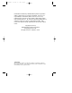
ISA-FINAL 3/31/98 4:06 PM Page c ABOUT THIS GUIDE This installation guide is for SMC's family of EZ Card™ 10 ISA Plug and Play Network Cards. The three models are as follows: Order Number Description SMC1660T twisted-pair card with RJ-45 connector SMC1660BT 2-port combo card with RJ-45 and BNC connectors SMC1660BTA 3-port combo card with RJ-45, BNC and AUI connectors Table 1.
ISA-FINAL 3/31/98 4:06 PM Page d PACKAGE CONTENTS Carefully unpack the contents of the package and check them against the checklist below: ✓ ✓ ✓ ✓ ✓ One EZ Card 10 ISA Network Card BNC T-Connector (combo models only) One Driver Diskette This User Guide SMC Warranty Registration Card — please complete and return this card to SMC Note: Network cards are sensitive to static electricity, which can damage their delicate electronic components.
ISA-FINAL 3/31/98 4:06 PM Page vii QUICK START Installing the Card 1. Power off your PC and remove its cover. 2. If you have purchased an optional boot ROM, plug the boot ROM into the socket on the card, making sure the notch on the memory device and that on the socket are in the same direction. 3. Select an available expansion slot and plug in the card. 4. Connect your card using the appropriate network connection (RJ-45, BNC or AUI). 5. Power on the PC. 6.
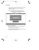
ISA-FINAL 3/31/98 4:06 PM Page viii QUICK START The configuration program is automatically invoked once the INSTALL command is entered and the Program Menu is displayed (see Figure 1). Note: This program may be run again by typing the following command at the DOS prompt while you are in the directory where the program is located: SMCINST Press Figure 1. Program Menu 3. Select Hardware Configuration from the Program Menu to display the Main Menu (see Figure 2). 4.
ISA-FINAL 3/31/98 4:06 PM Page ix QUICK START Figure 2. Main Menu Figure 3.
ISA-FINAL 3/31/98 4:06 PM Page x QUICK START Note: If you need to modify the current configuration and you are in a Jumperless (non-Plug and Play) environment, return to the Main Menu and select Manual Setup. In a Plug and Play environment, select the Default Setup option to automatically set the parameters. Refer to Chapter 2, “Hardware Settings” for more detailed information. 5. If you have made changes to the Card Configuration, the program prompts you to save these changes. 6. Run the Diagnostics.
ISA-FINAL 3/31/98 4:06 PM Page xi QUICK START Software Installation NetWare Client Operating System The following steps will be performed if you select “Yes” from the EZ Link screen: • the drivers and configuration files are copied • STARTNET.BAT and NET.CFG files are created • card’s components and corresponding cabling system are tested • network drivers are loaded • you are logged on to the nearest Novell server, which then prompts for your password 1. Select EZ Link from the Program Menu. 2.
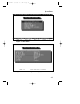
ISA-FINAL 3/31/98 4:06 PM Page xii QUICK START Other Operating Systems (including Windows95 and NT) 1. Select the Software Installation option from the Program Menu. The Software Installation Screen is displayed (see Figure 4). Figure 4. Software Installation Screen Menu Bar Commands - the menu bar below the title bar contains File, Action and Help pull-down menus.
ISA-FINAL 3/31/98 4:06 PM Page xiii QUICK START Note: Use the tab key to go to the next field and arrow keys to move the cursor up or down within a field. 2. Select the Vendor and corresponding network operating system from the screen. If the driver is not included in this menu, refer to the *.TXT file for a list of available drivers and instructions for installing these drivers. *.TXT files are provided in each subdirectory for last-minute changes and detailed driver installation instructions. 3.
ISA-FINAL 3/31/98 4:06 PM Page 1-1 TABLE OF CONTENTS Chapter 1 2 Hardware Description.................................. 1-1 LAN Connectors ................................................................. 1-1 LED Indicators.................................................................... 1-1 Link Status....................................................................... 1-2 Activity Status ................................................................. 1-2 Hardware Settings ............
ISA-FINAL 3/31/98 4:06 PM Page 1-2 TABLE OF CONTENTS D E Specifications................................................ D-1 General .............................................................................. D-1 Operating Environment ..................................................... D-2 EMC/Safety Compliance .................................................... D-2 Network Drivers................................................................. D-3 Glossary................................
ISA-FINAL 3/31/98 4:06 PM Page 1-3 TABLE OF CONTENTS List of Figures Figure 1. Program Menu................................................. vi Figure 2. Main Menu ...................................................... vii Figure 3. Current Configuration Display ....................... vii Figure 4. Software Installation Screen ........................... x Figure 1-1. LED Indicators................................................. 1-2 Figure 2-1. Default Setup.............................
ISA-FINAL 3/31/98 4:06 PM Page 1-5 CHAPTER 1 HARDWARE DESCRIPTION The SMC EZ Card 10 ISA models have two LED indicators and support from one to three types of network connections. LAN Connectors The EZ Card 10 ISA models support IEEE 802.3 10BASE-T, 10BASE2 and 10BASE5 standards.
ISA-FINAL 3/31/98 4:06 PM Page 1-6 HARDWARE DESCRIPTION 1660BTA 1660T 1660BT Figure 1-1. LED Indicators Link Status (Lnk) Color: Green Function: Twisted-pair link status indicator When lit, this LED indicates an active connection between the network card and a 10BASE-T hub or switch. Note: The Link Status LED does not monitor the condition of the BNC and AUI connections. When the card is configured for these connections, this LED is always lit.
ISA-FINAL 3/31/98 4:06 PM Page 1-7 CHAPTER 2 HARDWARE SETTINGS Default Setup The Default Setup option automatically allocates necessary I/O and IRQ resources to the card, then detects and corrects parameter settings which are in conflict with other devices installed on the host PC. If you have more than one Plug and Play card installed and you select Hardware Configuration from the Program Menu, you will be prompted to specify the card you want to configure.
ISA-FINAL 3/31/98 4:07 PM Page 1-8 HARDWARE SETTINGS Manual Setup This option is used for systems without Plug and Play support or when it is necessary to change the default settings. Figure 2-2. Manual Setup - Plug and Play Environment Figure 2-3.
ISA-FINAL 3/31/98 4:07 PM Page 1-9 HARDWARE SETTINGS Changing the Settings The following settings may be changed in the Plug and Play and Jumperless environments. Medium Type The transceiver setting depends on the type of card you are using. It should agree with the network cabling type. For combo cards, this program provides two media type selections: Auto Detect and AUI.
ISA-FINAL 3/31/98 4:07 PM Page 1-10 HARDWARE SETTINGS Interrupt (Jumperless Environment only) Select any available hardware interrupt in the range 2 to 15 from the displayed list. The card’s default interrupt setting is 3. The following table lists the XT and AT interrupt settings: IRQ XT AT 2 EGA/VGA EGA/VGA 3 COM2 COM2 4 COM1 COM1 5 Hard Disk Parallel Printer Port 10 N.A. Unused 11 N.A. Unused 12 N.A. Mouse for PS/2 15 N.A. Unused Table 2.2.
ISA-FINAL 3/31/98 4:07 PM Page 1-11 HARDWARE SETTINGS The boot ROM is disabled by default. When a boot ROM is installed on the card, you can enable the boot function by selecting a boot ROM address (i.e., C0000h, C4000h, C8000h, CC000h, D0000h, D4000h, D8000h or DC000h). Like all other card parameters, this value should be unique to your system. (You may need to temporarily disable EMM386 in your config.sys file to free-up space for the boot ROM.
ISA-FINAL 3/31/98 4:07 PM Page 1-13 APPENDIX A DIAGNOSTICS The installation program includes a diagnostics program for checking the card's components and the network cabling. The card may fail some tests due to various reasons – some of which may be easily remedied by the user. See Appendix B, Troubleshooting, on tips to isolate and solve common problems. Select the appropriate diagnostic from the Main Menu. Figure A-1.
ISA-FINAL 3/31/98 4:07 PM Page 1-14 DIAGNOSTICS Diagnose the Card To test the card’s components and its installation, select: • Diagnose the Adapter or • Diagnose EEPROM. The screen displays the PASSED or FAILED packet count for each test. If a test fails, press the spacebar to display the reason for failure and possible solutions. Note: These tests do not test the network's condition. Figure A-2.
ISA-FINAL 3/31/98 4:07 PM Page 1-15 DIAGNOSTICS Press space bar to continue Figure A-3. EEPROM Test Network Diagnostics To verify your card's ability to communicate with another device on the network, select Run Diagnostics on Network from the Main Menu. Set up at least one computer as a Responder and at least one as an Initiator. In the test, one PC generates test messages across the network. Another PC receives the test messages and echoes them back to the source PC.
ISA-FINAL 3/31/98 4:07 PM Page 1-16 DIAGNOSTICS Figure A-5. On-Network Diagnostics - Initiator Screen Figure A-6.
ISA-FINAL 3/31/98 4:07 PM Page 1-17 APPENDIX B TROUBLESHOOTING "Clean Boot" Many installation problems are caused by incompatible device drivers and resource conflicts. The best way to troubleshoot your installation is to boot your computer without the AUTOEXEC.BAT and CONFIG.SYS files. Reboot your computer using the BIOS Option, such as pressing , which allows you to bypass all startup files. Otherwise, create a bootable system diskette or rename AUTOEXEC.BAT and CONFIG.
ISA-FINAL 3/31/98 4:07 PM Page 1-18 TROUBLESHOOTING Problems and Solutions The following sections offer some helpful suggestions and tips to go about resolving some of the more common problems you may encounter during the installation process. Symptoms 1. Unshielded twisted-pair connection results in card failure; LNK (Link) LED indicator is off. 2. Running On-Board Diagnostics results in External Loopback Test failure in DOS environment. Possible Cause Invalid twisted-pair link Suggestions 1.
ISA-FINAL 3/31/98 4:07 PM Page 1-19 TROUBLESHOOTING Symptom The PC is unable to log into the network. Possible Causes 1. Bad cable connection. 2. Card not properly installed in computer slot. 3. Host PC’s slot is defective. 4. IRQ conflict. Suggestions 1. If you are using the RJ-45 connector, check the cabling for loose connection or wrong pin assignment. 2. Check to be sure the card is properly seated in the computer’s slot; it may have been accidentally loosened. 3.
ISA-FINAL 3/31/98 4:07 PM Page 1-21 APPENDIX C PIN ASSIGNMENTS RJ-45 Connector Pin Number Assignment Pin 1 Output Transmit Data + Pin 2 Output Transmit Data - Pin 3 Input Receive Data + Pin 6 Input Receive Data - Pin 4, 5, 7, 8 Reserved for other use Table C-1.
ISA-FINAL 3/31/98 4:07 PM Page 1-22 PIN ASSIGNMENTS AUI Connector Pin Number Assignment Pin 1 Control In Shield Pin 2 Control In A (CD +) Pin 3 Data Out A (TX +) Pin 4 Data In Shield Pin 5 Data In A (RX +) Pin 6 DC Power Common Pin 9 Control In B (CD -) Pin 10 Data Out B (TX-) Pin 11 Data Out Shield Pin 12 Data In B Pin 13 DC Power + Pin 14 Power Shield Pin 7, 8, 15 No connection Table C.2.
ISA-FINAL 3/31/98 4:07 PM Page 1-23 APPENDIX D SPECIFICATIONS General Network Interface RJ-45 (UTP Cable: EIA/TIA Categories 3, 4, 5) BNC (Coax Cable: RG-58 A/U or RG-58 C/U) AUI (Drop Cable) Standards Supported IEEE 802.3 and ISO/IEC 8802-3 10BASE-T (twisted-pair), 10BASE2 (thin coax) and 10BASE5 (thick coax) Hardware Compatibility IBM PC-XT, AT, 286, 386, 486, Pentium, PS2 Model 30, and compatible, ISA-bus computers.
ISA-FINAL 3/31/98 4:07 PM Page 1-24 SPECIFICATIONS Operating Environment Operating Temperature 0° to 55°C (32° to 131°F) Humidity 10% to 90% (non-condensing) Power Requirements On-board 10BASE Transceiver (RJ-45) Stand-by: +5 V / 110 mA Transmit: +5 V / 130 mA On-board 10BASE2 Transceiver (BNC) Stand-by: +5 V / 420 mA Transmit: +5 V / 470 mA External 10BASE5 MAU (AUI) Maximum: +12 V / 500 mA EMC/Safety Compliance FCC Class B CDOC Class B CISPR 22:1985 Class B EN55022:1987 Class B AS/NZS (1992) VCCI Clas
ISA-FINAL 3/31/98 4:07 PM Page 1-25 SPECIFICATIONS Network Drivers NetWare ODI Drivers NetWare 3.x, 4.x, 4.11 NetWare LAN WorkPlace TCP/IP Novell LAN Analyzer for NetWare NDIS 2.0 Drivers IBM LAN Server IBM LAN Support Program DEC PATHWORKS Sun PC-NFS IBM TCP/IP for DOS & OS/2 Microsoft LAN Manager NDIS 3.0 Drivers Microsoft Windows for Workgroups 3.11 Windows 95 Windows NT 3.x Windows NT 4.0 Unix Drivers SCO OpenServer 5.
ISA-FINAL 3/31/98 4:07 PM Page 1-27 APPENDIX E GLOSSARY 10BASE-T IEEE specifications for 10 Mbps Ethernet on twisted-pair cable (100 Ω UTP). The maximum cable length for a point-to-point connection is 100 m (328 ft.) and the maximum number of nodes is 1024. 10BASE2 IEEE specifications for 10 Mbps Ethernet on thin coaxial cable (50 Ω RG-58). A cable segment can be up to 185 m (607 ft.) long and have a maximum of 30 nodes. 10BASE5 IEEE specification for 10 Mbps Ethernet on thick D-type cable.
ISA-FINAL 3/31/98 4:07 PM Page 1-28 GLOSSARY Broadcast The process of sending a message to all stations on a network. Collision Condition in which two packets transmitted over a medium interfere with each other. Their interference makes both unintelligible. The transmitting devices have to halt transmission for a random period of time before trying to send data again. Note that collisions do not occur on full-duplex connections.
ISA-FINAL 3/31/98 4:07 PM Page 1-29 GLOSSARY NetWare Novell's Network Operating System, which provides the ability to transparently share services across dissimilar platforms. Uses the NetWare Core Protocol (NCP), Internetwork Packet Exchange (IPX), and Sequential Packet Exchange (SPX) protocols. RJ-45 Connector Most common terminator for twisted-pair cable. TCP/IP Transmission Control Protocol/Internet Protocol.
ISA-FINAL 3/31/98 4:07 PM Page 1-31 INDEX A I Activity Status 1-2 AUI Connector C-2 Interrupt 2-4 I/O Base Address B L BIOS Option B-1 Boot ROM v, 2-4 LAN Connector 1-1 LED Indicators 1-1 Link (LNK) LED 1-2 Link Status Indicator 1-2 C Card Installation v Clean Boot B-1 D Default Setup 2-1 Diagnose Card A-2 Diagnose EEPROM A-2 Driver Diskette iv, v E EMC/Safety Co D-3 F Full Duplex 2-3 H Hardware Configuration vi Hardware Description 1-1 Hardware Configuration 2-1 2-3 M Manual Setup 2-2 Me
ISA-FINAL 3/31/98 4:07 PM Page 1-32 INDEX S Specifications D-1 Standards Conformance D-2 System Configuration D-1 T Troubleshooting B-1 W Warranty Registration Card I-2 iv
ISA-FINAL 3/31/98 4:07 PM Page 1-33 Limited Warranty HARDWARE: Standard Microsystems Corporation (“SMC”) warrants its EZ Card 10 ISA network cards to be free from defects in workmanship and materials, under normal use and service, for the following lengths of time from the date of purchase from SMC or its Authorized Reseller: EZ Card 10 ISA Network Cards........................................
ISA-FINAL 3/31/98 4:07 PM Page 1-34 LIMITED WARRANTY WARRANTIES EXCLUSIVE: IF AN SMC PRODUCT DOES NOT OPERATE AS WARRANTED ABOVE, CUSTOMER’S SOLE REMEDY SHALL BE REPAIR, REPLACEMENT OR REFUND OF THE PURCHASE PRICE PAID, AT SMC’S OPTION.
ISA-FINAL 3/31/98 4:07 PM Page 1-35 COMPLIANCES FCC Class B This equipment has been tested and found to comply with the limits for a Class B digital device, pursuant to Part 15 of the FCC Rules. These limits are designed to provide reasonable protection against harmful interference in a residential installation. This equipment generates, uses and can radiate radio frequency energy and, if not installed and used in accordance with instructions, may cause harmful interference to radio communications.
ISA-FINAL 3/31/98 4:07 PM Page 1-36 COMPLIANCES EC Conformity This information technology product was found to comply with EC General Directives 89/336/EEC and 73/23/EEC. European Headquarters: Standard Microsystems Corporation (Europe) Limited 1st Floor, Pyramid House, Easthampstead Road Bracknell, Berkshire RG12 1NS, United Kingdom This product conforms to the following specifications: EMC: EN55022(1988)/CISPR-22(1985) Class B IEC1000-4-2 4kV CD, 8kV AD IEC1000-4-3 3V/m IEC1000-4-4 1kV-(power line) 0.
EZ Card ISA Cover 3/31/98 5:47 PM Page 1 FOR TECHNICAL SUPPORT, CALL: From U.S.A. and Canada (8:30 AM - 8:00 PM Eastern Time) (800) SMC-4-YOU; (516) 435-6250; (516) 434-9314 (Fax) From Europe (8:00 AM - 5:30 PM UK Greenwich Mean Time) 44 (0) 1344-420068; 44 (0) 1344-418835 (Fax) Bulletin Board Services (BBS) Modem settings: 9600,8,n,1 New York: (516) 434-3162 (connect speed up to 14,400) Germany: 49 (0) 89 92861-240 France: 33 (1) 39.73.57.