SMC2582W-B
Copyright Information furnished by SMC Networks, Inc. (SMC) is believed to be accurate and reliable. However, no responsibility is assumed by SMC for its use, nor for any infringements of patents or other rights of third parties which may result from its use. No license is granted by implication or otherwise under any patent or patent rights of SMC. SMC reserves the right to change specifications at any time without notice. Copyright © 2003 by SMC Networks, Inc.
Federal Communication Commission Interference Statement This equipment has been tested and found to comply with the limits for a Class B digital device, pursuant to Part 15 of the FCC Rules.These limits are designed to provide reasonable protection against harmful interference in a residential installation.This equipment generates, uses and can radiated radio frequency energy and, if not installed and used in accordance with the instructions, may cause harmful interference to radio communications.
EC Conformance Declaration - Class B SMC contact for these products in Europe is: SMC Networks Europe, Edificio Conata II, Calle Fructuós Gelabert 6-8, Planta 2, 08970 - Sant Joan Despí, Barcelona, Spain.
8. Beachten Sie beim Anschluß an das Stromnetz die Anschlußwerte. 9. Verlegen Sie die Netzanschlußleitung so, daß niemand darüber fallen kann. Es sollte auch nichts auf der Leitung abgestellt werden. 10. Alle Hinweise und Warnungen, die sich am Gerät befinden, sind zu beachten. 11.Wird das Gerät über einen längeren Zeitraum nicht benutzt, sollten Sie es vom Stromnetz trennen. Somit wird im Falle einer Überspannung eine Beschädigung vermieden. 12.
1. Introduction 1.1. Overview The SMC2582W-B is a versatile device that can be configured to be in one of the 3 operational modes—Access Point, Bridge Master, and Bridge Slave—for various wireless bridging applications. With the convenient Web-based user interface, a network administrator can easily and clearly manage the SMC2582W-B. In Chapter 2, we describe the steps to install and configure a newly acquired SMC2582W-B. Following the steps, the SMC2582W-B can be quickly set up to work.
• MAC-address-based access control. When the SMC2582W-B is in AP or Bridge Master mode, it can be configured to block unauthorized STAs or Bridge Slaves based on MAC (Media Access Control) addresses.The ACL (Access Control List) can also be downloaded from a TFTP server. • Transmit power control. Transmit power of the SMC2582W-B can be adjusted to control the area of coverage. • Link integrity.
• Management • Web-based management for configuring and monitoring SMC2582W-B via a Web-Browser. • SNMP. SNMP (Simple Network Management Protocol) MIB I, MIB II, IEEE 802.1d, and Private Enterprise MIB are supported. • UPnP. The SMC2582W-B responds to UPnP discovery messages so that a Windows XP user can locate the SMC2582W-B in My Network Places and use a Web browser to configure it. • Telnet. The SMC2582W-B can be managed by Telnet. • System log. For system operational status monitoring. • Local log.
1.3. LED Definitions There are several LED indicators on the housing of the SMC2582W-B.They are defined as follows: • • • • ALV: Alive. Blinks when the SMC2582W-B is working normally. RF: IEEE 802.
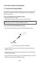
2. First-Time Installation and Configuration 2.1. Selecting a Power Supply Method The SMC2582W-B can be powered by either the supplied power adapter or the optional SMCPWRINJ3 EliteConnect™ Power Injector.The SMC2582W-B automatically selects the suitable power depending on your decision. To power the SMC2582W-B by the supplied power adapter: 1. Plug the power adapter to an AC socket. 2. Plug the connector of the power adapter to the power jack of the SMC2582W-B.
Fig. 2. Connecting Ethernet cables to SMCPWR-INJ3. 5. Check the “ACTIVE”LED: if power is successfully fed into the SMC2582W-B, the “ACTIVE”LED will be on (Red light); otherwise, the “ACTIVE”LED will be off. 6. If the electricity current is over the normal condition (Io°÷1.0 A), the “ACTIVE”LED will flash (Red light). NOTE: SMCPWR-INJ3 is specially designed for “SMC2582W-B EliteConnect™ 2.4GHz 11Mbps Wireless Bridge.The use of SMCPWR-INJ3 with other Ethernet-ready devices that are not compliant to 802.
Fig. 3. Mounting the SMC2582W-B on a wall. 2.3. Preparing for Configuration For you to configure an SMC2582W-B, a managing computer with a Web browser is needed. For first-time configuration of an SMC2582W-B, an Ethernet network interface card (NIC) should have been installed in the managing computer. For maintenance-configuration of a deployed SMC2582W-B, either a wireless computer or a wired computer can be employed as the managing computer.
Fig. 4. Connecting a managing computer and an SMC2582W-B via Ethernet. You can use either a cross-over Ethernet cable (included in the package) or a switch/hub with 2 normal Ethernet cables. NOTE: One connector of the Ethernet cable must be plugged into the LAN/CONFIG Ethernet jack of the SMC2582W-B for configuration. 2.3.2.
2.4. Configuring the SMC2582W-B After the IP addressing is configured, launch a Web browser on the managing computer.Then, go to “http://192.168.2.50” to access the Start page of the SMC2582W-B’s Web-based management interface. TIP: For maintenance configuration of an SMC2582W-B, the SMC2582W-B can be reached by its host name using a Web browser. For example, if the SMC2582W-B is named “AP”, you can use the URL “http://AP”to access the Web-based management interface of the SMC2582W-B. 2.4.1.
Fig. 6.The Start page. 2.4.2. Step 1: Selecting an Operational Mode Fig. 7. Operational modes settings.
The SMC2582W-B supports 3 operational modes for meeting various wireless connectivity requirements: • Access Point (AP). The AP mode enables IEEE 802.11 Stations (STAs) to automatically associate with it via the standard IEEE 802.11 association process. In addition, the IEEE 802.11 WDS (Wireless Distribution System) technology can be used to manually establish wireless links between two APs or between an AP and a Bridge Master. • Bridge Master (BM).
Select an operational mode and click Save at the bottom of this page, and then you are brought back to the start page. 2.4.3. Step 2: Configuring TCP/IP Settings Fig. 8.TCP/IP settings. Go to the TCP/IP Addressing section to configure IP address settings.The IP address can be manually set or automatically assigned by a DHCP server on the LAN. If you are manually setting the IP address, Subnet mask, and Default gateway settings, set them appropriately, so that they comply with your LAN environment.
If the SMC2582W-B was configured to be in AP or Bridge Master mode, and you want to use WDS to establish inter-SMC2582W-B wireless links, configure the WDS settings. Fig. 10.Wireless Distribution System settings. To enable a WDS link: 1. Specify the MAC address of the AP or bridge at the other end of the WDS link. 2. Select the corresponding Enabled check box. For example, assume you want two SMC2582W-Bs with MAC addresses 00-02-65-01-62-C5 and 0002-65-01-62-C6 to establish a WDS link between them.
Fig. 12. Network topology containing a loop. When you are finished, click Save at the bottom of this page, and then you are brought back to the start page. 2.4.5. Step 4: Reviewing and Applying Settings Fig. 13. Settings changes are highlighted in red. On the start page, you can review all the settings you have made. Changes are higlighted in red. If they are ok, click Restart to restart the SMC2582W-B for the new settings to take effect.
2.5. Deploying the SMC2582W-B After the settings have been configured, deploy the SMC2582W-B to the field application environment. Connect the SMC2582W-B to an Ethernet LAN through an Ethernet switch/hub. If external high-gain directional antennas are used for a long-range wireless bridging application, it may be difficult to align the antennas. Here is a suggestion for antenna alignment. To adjust the alignments of a pair of SMC high-gain antennas: 1. Connect each SMC2582W-B to a computer via Ethernet. 2.
3. Using Web-Based Management In this chapter, we’ll explain each Web management page of the SMC2582W-B. 3.1. Overview Fig. 15.The Start page. 3.1.1. Menu Structure The left side of the start page contains a menu for you to carry out commands. Here is a brief description of the hyperlinks on the menu: • Home. For going back to the start page. • Status. Status information. • Wireless Clients.The status of the wireless clients (STAs and Bridge Slaves) currently associated with the SMC2582W-B.
• System Log. System events log. • General. Global operations. • Operational Mode. Operational mode settings. • Password. For gaining rights to change the settings of the SMC2582W-B. • Firmware Tools. For upgrading the firmware of the SMC2582W-B, backing up and restoring configuration, and configuration reset settings of the SMC2582W-B. • TCP/IP. TCP/IP- related settings. • Addressing. IP address settings for the SMC2582W-B to work with TCP/IP. • DHCP Server.
If you click Save, the start page will reflect the fact that the configuration settings have been changed by showing two buttons—Restart and Cancel. In addition, changes are highlighted in red. Clicking Cancel discards all the changes. Clicking Restart restarts the SMC2582W-B for the settings to take effect. Fig. 17. Settings have been changed. 3.1.3. Home and Refresh Commands Fig. 18. Home and Refresh.
3.2.2. Current DHCP Mappings Fig. 20 Current DHCP mappings. On this page, all the current static or dynamic DHCP mappings are shown. A DHCP mapping is a correspondence relationship between an IP address assigned by the DHCP server and a computer or device that obtains the IP address. A computer or device that acts as a DHCP client is identified by its MAC address. A static mapping indicates that the DHCP client always obtains the specified IP address from the DHCP server.
3.3. General Operations 3.3.1. Selecting an Operational Mode Fig. 22. Operational modes settings. The SMC2582W-B supports 3 operational modes for meeting various wireless connectivity requirements: • Access Point (AP). The AP mode enables IEEE 802.11 Stations (STAs) to automatically associ ate with it via the standard IEEE 802.11 association process. In addition, the IEEE 802.
between an IEEE 802.11 Station (STA) and an IEEE 802.11 Access Point (AP). An STA is usually a client computer (PC or PDA) with a WLAN network interface card (NIC). • WDS. This type of wireless link is specified in the IEEE 802.11 standard for communication between two IEEE 802.11 APs.Wireless packets transmitted along the WDS link comply with the IEEE 802.11 WDS (Wireless Distribution System) format at the link layer. • BM-BS.
backup, and configuration restore can be achieved via HTTP or TFTP.The HTTP-based way is suggested because it’s more user-friendly. However, due to different behavior of different Web browser types and versions, HTTP-based firmware management operations may not work properly with some Web browsers. If you cannot successfully perform HTTP-based firmware management operations with your Web browser, try the TFTP-based method. 3.3.3.1. Upgrading Firmware by HTTP Fig. 25. Firmware upgrade by HTTP.
To restore configuration of the SMC2582W-B by HTTP: 1. Click Browse and then select a correct configuration .hex file.You have to make sure the file name is the SMC2582W-B’s MAC address.The firmware file path will be shown in the Firmware file name text box. 2. Click Restore to upload the configuration file to the SMC2582W-B. 3.3.3.3. Upgrading Firmware by TFTP Fig. 28.TFTP server settings.
Fig. 30.TFTP Server. NOTE: After the dialog box of the TFTP server program appears, be sure to specify the working folder within which the downloaded firmware files reside. NOTE: Make sure the Accept read requests check box of TFTP Server is selected. NOTE: The LAN IP address of the SMC2582W-B and the IP address of the TFTP server must be in the same IP subnet for TFTP to work.
To back up configuration of the SMC2582W-B by TFTP: 1. Get a computer that will be used as a TFTP server and as a managing computer to trigger the backup process. 2. Connect the computer and one of the LAN Ethernet switch port with a normal Ethernet cable. 3. Configure the IP address of the computer so that the computer and the SMC2582W-B are in the same IP subnet. 4. On the computer, run the TFTP Server utility.
3.3.3.5. Resetting Configuration to Factory Defaults Fig. 32. Configuration reset. Clicking the Reset button resets the device configuration to factory defaults. WARNING: Think twice before clicking the Reset button.You’ll lose all your current configuration settings. 3.4. Configuring TCP/IP Related Settings 3.4.1. Addressing Fig. 33.TCP/IP settings. The IP address of the SMC2582W-B can be manually set (Set Manually) or automatically assigned by a DHCP server on the LAN (Obtain from a DHCP Server).
3.4.2. DHCP Server 3.4.2.1. Basic Fig. 34. Basic DHCP server settings. The SMC2582W-B can automatically assign IP addresses to client computers by DHCP. In this section of the management page, you can specify the Default gateway, Subnet mask, Primary DNS server, and Secondary DNS server settings that will be sent to a client at its request. Additionally, you can specify the first IP address that will be assigned to the clients and the number of allocatable IP addresses.
always assigned the same IP address. To always assign a static IP address to a specific DHCP client: 1. Specify the MAC address of the DHCP client and the IP address to be assigned to it.Then, give a description of this mapping. 2. Select the corresponding Enabled check box. 3.5. Configuring IEEE 802.11b-Related Settings 3.5.1. Communication 3.5.1.1. Basic Basic IEEE 802.11b-related communication settings include AP functionality, Channel number, Network name (SSID), Data rate, and Transmit power. Fig.
3.5.1.2. Link Integrity Fig. 37. Link integrity settings. When the SMC2582W-B is in AP or Bridge Master mode and the Ethernet LAN interface is detected to be disconnected from the wired network, all currently associated wireless clients (STAs and Bridge Slaves) are disassociated by the SMC2582W-B and no wireless client can associate with the SMC2582W-B.The detection mechanism is based on pinging the IP address specified in Reference host. 3.5.1.3. Wireless Distribution System Fig. 38.
NOTE: An SMC2582W-B can have up to 6 WDS links to other APs or wireless bridges. Fig. 40.Wireless Distribution System settings. To enable a WDS link: 3. Specify the MAC address of the AP or bridge at the other end of the WDS link. 4. Select the corresponding Enabled check box. For example, assume you want two SMC2582W-Bs with MAC addresses 00-02-65-01-62-C5 and 0002-65-01-62-C6 to establish a WDS link between them.
Fig. 42. Network topology containing a loop. 3.5.2. Security IEEE 802.11b security settings include SSID broadcasts, Wireless client isolation, Security mode, IEEE 802.11 Authentication algorithm,WEP keys,MAC-Address-Based Access Control. 3.5.2.1. Basic Fig. 43. Basic IEEE 802.11b security settings. For security reasons, it is highly recommended that the security mode be set to options other than Open System.
SMC2582-Bs in the same IP subnet is blocked.The behaviors are illustrated in the following figures. Fig. 44. Behavior of the “This AP Only”wireless client isolation option. Fig. 45. Behavior of the “All APs on This Subnet”wireless client isolation option. As illustrated in Fig 44 when AP 1 and AP 2 are using the “This AP Only”option, wireless traffic between STA 1 and STA 2 is blocked by AP 1, while wireless traffic between STA 2 and STA 3, which are associated with different APs, is still allowed.
algorithm setting is provided for better compatibility with wireless client computers with various WLAN network adapters.There are three options available, including Open System, Shared Key, and Auto. When WEP is enabled by a security mode, the Key length can be specified to be 64 Bits or 128 Bits. The Selected key setting specifies the key to be used as a send-key for encrypting traffic from the local device side to the remote device side.
4. Repeat Step 3 for each other wireless client. To grant wireless clients’ access to the wireless network: 1. Select Enabled from the Functionality drop-down list. 2. Set the Access control type to inclusive. 3. Specify the MAC address of a wireless client to allow access, and then click Add. 4. Repeat Step 3 for each other wireless client. To delete an entry in the access control table: • Click Delete next to the entry. NOTE: The size of the access control table is 64. Fig. 47. MAC ACL download settings.
3.6. Configuring Advanced Settings 3.6.1. Packet Filters The SMC2582W-B provides layer 2 (Ethernet Type Filters), layer 3 (IP Protocol Filters), and layer 4 (TCP/UDP Port Filters) filtering capabilities.The configuration processes for the filters are similar. Functionality: whether this filtering capability is enabled or disabled. Policy for matched packets: how a matched packet is processed—discard or pass. To enable a filtering rule: select the check box to the left of the rule. 3.6.1.1.
source IP address range (Source IP Address AND Source Subnet Mask), and destination IP address range (Destination IP Address AND Destination Subnet Mask). A source (destination) IP address range is determined by performing an AND operation on the source (destination) IP address field and the source (destination) subnet mask field. For example, if the source IP address field is 192.168.0.1 and the source subnet mask field is 255.255.255.0, the resultant source IP address range is 192.168.0.0 to 192.168.0.
3.6.2.3. System Log Fig. 53. System log settings. System events can be logged to the on-board RAM of the SMC2582W-B (Local log) or sent in the form of SNMP trap (Remote log by SNMP trap) or BSD Syslog (Remote log by BSD Syslog) to a remote SNMP trap monitoring server or remote Syslog server, respectively. See the next subsection for more information about SNMP trap settings. Set the IP address of the Syslog server in the Syslog server IP address text box.
To specify a trap target: 1. Type the IP address of the target host. 2. Type the Community for the host. 3. Select the corresponding check box next to the IP address text box.
Appendix A: Default Settings TIP: Press the Default switch on the housing of a powered-on SMC2582W-B to reset the configuration settings to factory-default values.
Appendix B: Troubleshooting Check the following first: • Make sure that the power of the SMC2582W-B is on and the Ethernet cables are connected firmly to the RJ-45 jacks of the SMC2582W-B. • Make sure that the LED ALV of the SMC2582W-B is blinking to indicate the SMC2582W-B is working. • Make sure the types of the Ethernet cables are correct. Recall that there are two types— normal and crossover. B-1: Wireless Settings Problems • The wireless client computer cannot associate with an SMC2582W-B.
For a wireless client computer to communicate with a correspondent host on the Internet by the host’s domain name (e.g. http://www.wi-fi.com), it first sends a DNS request to a DNS server on the Internet.The DNS request travels first to the AP, then the AP relays this request to the default gateway of the client computer. Finally, this request is forwarded by the gateway to the DNS server on the Internet.
• Solve the preceding problem first. • Are the IP address of the SMC2582W-B and the IP address of the client computer in the same IP subnet? • If you cannot find any incorrect settings of the SMC2582W-B, the default gateway may be really down or there are other communication problems on the network backbone. • The DNS server(s) of the client computer do not respond to ping from the client computer. • Solve the preceding problems first.
• My SMC2582W-B stops working and does not respond to Web management requests. • The firmware of the SMC2582W-B may be stuck in an incorrect state. • Unplug the power connector from the power jack, and then re-plug the connector to restart the SMC2582W-B. • Contact our technical support representatives to report this problem. • If this happens after a failed firmware upgrade process, the firmware of the SMC2582W-B may have been corrupted.
Appendix D: Technical Specifications D-1: SMC2582W-B Wireless Bridge Standards: 802.11b 802.3 802.3u 802.3af Data rate & modulation: CCK@11/5.5Mbps, DQPSK@2Mbps and DBSK@1Mbps Radio Technology: Direct Sequence Spread Spectrum (DSSS) Operating Range: Up to 1,500 feet Frequency range: 2.400 ~ 2.4834 GHz (North America) 2.400 ~ 2.4970 GHz (Japan) 2.412 ~ 2.
Interface: 10/100 Mbps RJ-45 Connector RS-232c Serial Connector 802.11b WLAN Security: 64/128-bit WEP MAC address filtering Disabled SSID broadcast Configuration and Management Web-browser Telnet TFTP SNMP Syslog Event Logging LEDs Power LAN WLAN Alive Environmental Temperature: Operating (0~55oC), storage (-20~70oC) Humidity: 5% to 95% non-condensing in storage Electromagnetic Compatibility FCC Class B Industry Canada CE ETS 300.328; ETS 300 826 Dimensions (without antenna): 6.75”x 5.5 “ x 1.25” Weight: 0.
D-2: SMCPWR-INJ3 Power Injector Input Power Requirements: AC Input Voltage AC Frequency AC Input Current : 90 – 264Vac : 47 – 63 Hz : 2A at 100Vac, 1A at 240Vac, (-48Vdc) Power over LAN output Specification: Pin Assignments and Polarity Output Voltage : (+) 4/5 (–) 7/8 : Aggregate Power:50W (48Vdc) Mechanical Requirement: Dimensions : 4”x 5.5”x 1.5” Weight: : 1.38 Lbs Indicators: System Indicator: AC Power (Green) Power Active (Red) 0.05 A°’Io°’0.8 A Over Current Protection (Red, Flash) Io°÷1.
FOR TECHNICAL SUPPORT, CALL: From U.S.A. and Canada (24 hours a day, 7 days a week) (800) SMC-4-YOU; Phn: (949) 679-8000; Fax: (949) 679-1481 From Europe : Contact details can be found on www.smc-europe.com or www.smc.com INTERNET E-mail addresses: techsupport@smc.com european.techsupport@smc-europe.com Driver updates: http://www.smc.com/index.cfm?action=tech_support_drivers_downloads World Wide Web: http://www.smc.com/ http://www.smc-europe.com/ For Literature or Advertising Response, Call: U.S.A.