
User's Manual


6
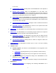
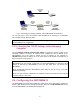
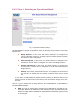
To SMC2586W-G From Etherne t Device
Fig. 2. Connecting Ethernet cables to SMCPWR-INJ3.
5. Check the “ACTIVE” LED: if power is successfully fed into the SMC2585W-G, the “AC-
TIVE” LED will be on (Red light); otherwise, the “ACTIVE” LED will be off.
6. If the electricity current is over the normal condition (Io>1.0 A), the “ACTIVE” LED will
flash (Red light).
NOTE: SMCPWR-INJ3 is specially designed for “SMC2585W-G EliteConnect™ 2.4GHz
11Mbps Wireless Bridge. The use of SMCPWR-INJ3 with other Ethernet-ready devices that
are not compliant to IEEE 802.3af may cause damage to the devices.
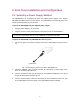
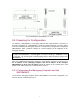
2.2. Mounting the SMC2585W-G on a Wall
The SMC2585W-G is wall-mountable.
1. Stick the supplied sticker for wall-mounting.
2. Use a
φ7.0mm driller to drill a 25mm-deep hole at each of the cross marks.
3. Plug in a supplied plastic conical anchor in each hole.
4. Screw a supplied screw in each plastic conical anchor for a proper depth so that the
SMC2585W-G can be hung on the screws.
5. Hang the SMC2585W-G on the screws.