TigerSwitch 10/100 8-Port Fast Ethernet Switch ◆ ◆ ◆ ◆ ◆ ◆ ◆ ◆ ◆ ◆ ◆ 8 10BASE-T/100BASE-TX ports, 1 1000BASE-T port Optional 100BASE-FX or 1000BASE-X modules 5.
TigerSwitch 10/100 Management Guide From SMC’s Tiger line of feature-rich workgroup LAN solutions 38 Tesla Irvine, CA 92618 Phone: (949) 679-8000 May 2003 Pub.
Information furnished by SMC Networks, Inc. (SMC) is believed to be accurate and reliable. However, no responsibility is assumed by SMC for its use, nor for any infringements of patents or other rights of third parties which may result from its use. No license is granted by implication or otherwise under any patent or patent rights of SMC. SMC reserves the right to change specifications at any time without notice. Copyright © 2003 by 38 Tesla Irvine, CA 92618 All rights reserved.
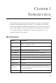
CONTENTS 1 Introduction . . . . . . . . . . . . . . . . . . . . . . . . . . . . . . . . . .1-1 Key Features . . . . . . . . . . . . . . . . . . . . . . . . . . . . . . . . . . . . . . . . . . . . . . . 1-1 Description of Software Features . . . . . . . . . . . . . . . . . . . . . . . . . . . . . . 1-2 System Defaults . . . . . . . . . . . . . . . . . . . . . . . . . . . . . . . . . . . . . . . . . . . . 1-4 2 Initial Configuration . . . . . . . . . . . . . . . . . . . . . . . . . .
CONTENTS Configuring Dynamic Trunks . . . . . . . . . . . . . . . . . . . . . . . . . . Aggregator Setting . . . . . . . . . . . . . . . . . . . . . . . . . . . . . . . . Aggregator Information . . . . . . . . . . . . . . . . . . . . . . . . . . . State Activity . . . . . . . . . . . . . . . . . . . . . . . . . . . . . . . . . . . . Forwarding and Filtering . . . . . . . . . . . . . . . . . . . . . . . . . . . . . . . . . . . . Configuring Multicast Filtering . . . . . . . . . . . . . . . . . . . . . . . .
CONTENTS Status and Counters Menu . . . . . . . . . . . . . . . . . . . . . . . . . . . . . . . . . . . . 4-6 Displaying Connection Status . . . . . . . . . . . . . . . . . . . . . . . . . . . 4-7 Showing Port Statistics . . . . . . . . . . . . . . . . . . . . . . . . . . . . . . . . . 4-8 Displaying System Information . . . . . . . . . . . . . . . . . . . . . . . . . . 4-9 Switch Static Configuration Menu . . . . . . . . . . . . . . . . . . . . . . . . . . . . . 4-10 Administration Configuration Menu . . .
CONTENTS Link Access Control Protocol Menu . . . . . . . . . . . . . . . . . . . . . Configuring the Aggregator Setting . . . . . . . . . . . . . . . . . . Setting the State Activity . . . . . . . . . . . . . . . . . . . . . . . . . . . Displaying Aggregator Information . . . . . . . . . . . . . . . . . . Reboot Switch Menu . . . . . . . . . . . . . . . . . . . . . . . . . . . . . . . . . . . . . . Set Logout Timer Menu . . . . . . . . . . . . . . . . . . . . . . . . . . . . . . . . . . . . .
CHAPTER 1 INTRODUCTION This switch provides a broad range of features for Layer 2 switching. It includes a management agent that allows you to configure the features listed in this manual. The default configuration can be used for most of the features provided by this switch. However, there are many options that you should configure to maximize the switch’s performance for your particular network environment.
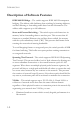
INTRODUCTION Description of Software Features IEEE 802.1D Bridge – The switch supports IEEE 802.1D transparent bridging. The address table facilitates data switching by learning addresses, and then filtering or forwarding traffic based on this information. The address table supports up to 6K addresses. Store-and-Forward Switching – The switch copies each frame into its memory before forwarding them to another port.
DESCRIPTION OF SOFTWARE FEATURES • Simplify network management for node changes/moves by remotely configuring VLAN membership for any port, rather than having to manually change the network connection. • Provide data security by restricting all traffic to the originating VLAN. Port Mirroring – The switch can unobtrusively mirror traffic from any port to a monitor port. You can then attach a protocol analyzer or RMON probe to this port to perform traffic analysis and verify connection integrity.
INTRODUCTION Multicast Filtering – Specific multicast traffic can be assigned to its own VLAN to ensure that it does not interfere with normal network traffic and to guarantee real-time delivery by setting the required priority level for the designated VLAN. The switch uses IGMP Snooping and Query to manage multicast group registration. System Defaults The following table lists some of the basic system defaults. Function Parameter Default IP Settings IP Address 0.0.0.0 Subnet Mask 0.0.0.
SYSTEM DEFAULTS Function Parameter Default Spanning Tree Protocol Status Enabled (Defaults: All values based on IEEE 802.
INTRODUCTION 1-6
CHAPTER 2 INITIAL CONFIGURATION Connecting to the Switch Configuration Options The switch includes a built-in network management agent. The agent offers a variety of management options, including SNMP, RMON, and a Web-based interface. A PC may also be connected directly to the switch for configuration and monitoring via the console menu. Note: The IP address for this switch is unassigned by default. To change this address, see “Setting an IP Address” on page 2-5.
INITIAL CONFIGURATION The switch’s console menu, Web Interface, and SNMP agent allow you to perform the following management functions: • • • • • • • • • • • • • • • • Set user name and password Set an IP interface for management access (console menu only) Configure SNMP parameters Enable/disable any Ethernet port Set the speed/duplex mode for any port Configure up to 255 IEEE 802.
CONNECTING TO THE SWITCH 2. Connect the other end of the cable to the RS-232 serial port on the switch. 3. Make sure the terminal emulation software is set as follows: • • • • • Select the appropriate serial port (COM port 1 or COM port 2). Set the data rate to 9600 baud. Set the data format to 8 data bits, 1 stop bit, and no parity. Set flow control to none. Set the emulation mode to VT100. Note: Once you have set up the terminal correctly, the console login screen will be displayed.
INITIAL CONFIGURATION Basic Configuration Console Connection Access to the console menu is controlled by a user name and password. The default setting is “admin” for both the user name and password. To log into the console menu, perform these steps: 1. Enter “admin” at the user name prompt. 2. Enter “admin” at the password prompt. (The password characters are not displayed on the console screen.) The session is opened and the Main Menu displays.
BASIC CONFIGURATION 4. Select “Change Password” and press . • • • Type the old password and press . Type the new password and press . Then re-enter the new password for verification, press . Setting an IP Address You must establish IP address information for the switch to obtain management access through the network. You can manually assign an IP address to the switch.
INITIAL CONFIGURATION To assign an IP address to the switch, complete the following steps: 1. Navigate from the Main Menu to – Switch Static Configuration, Administration Configuration, and then IP Configuration. 2. Select , type in the IP Address, Subnet Mask, and Gateway. Press after each item. Press to return to the action bar at the bottom of the screen. Select and press any key to continue. (The IP addresses shown below are merely examples.
BASIC CONFIGURATION Enabling SNMP Management Access The switch can be configured to accept management commands from Simple Network Management Protocol (SNMP) applications such as SMC’s EliteView. You also can configure the switch to generate SNMP traps. When SNMP management stations send requests to the switch (either to return information or to set a parameter), the switch provides the requested data or sets the specified parameter.
INITIAL CONFIGURATION 4. Use the scroll-bar to toggle the Write Access Field to “Restricted” or “Unrestricted.” 5. Press to return to the action bar at the bottom of the screen. Select and press any key to continue. (The community string shown below is an example.) TigerSwitch 10/100 : ===================== Add SNMP Community Community Name :private Write Access actions-> Tab=Next Item 2-8 :Unrestricted Select the action menu.
CHAPTER 3 CONFIGURING THE SWITCH Using the Web Interface This switch provides an embedded HTTP Web agent. Using a Web browser you can configure the switch and view statistics to monitor network activity. The Web agent can be accessed by any computer on the network using a standard Web browser (Internet Explorer 5.0 or above, or Netscape Navigator 6.2 or above.) Note: You can also use the console menu to manage the switch over a serial connection to the console port or via Telnet.
CONFIGURING THE SWITCH Navigating the Web Browser Interface To access the Web-browser interface you must first enter a user name and password. The administrator has Read/Write access to all configuration parameters and statistics. The default user name and password for the administrator is “admin.” Home Page When your Web browser connects with the switch’s Web agent, the home page is displayed as shown below.
PANEL DISPLAY Configuration Options Configurable parameters have a dialog box or a drop-down list. Once a configuration change has been made on a page, be sure to click on the “Apply” button to confirm the new setting. The following table summarizes the Web page configuration buttons. Button Action Apply Sets specified values to the system for the displayed page. Default Cancels specified values and restores current values prior to pressing “Apply.
CONFIGURING THE SWITCH Main Menu Using the onboard Web agent, you can define system parameters, manage and control the switch, or monitor network conditions. The following table briefly describes the selections available from this program.
MAIN MENU Menu Description VLAN Configuration Basic Port VID Page 3-27 Configures VLAN groups, including name, identifier, and if limited to a specific protocol 3-28 3-29 Sets port VID and ingress filters 3-32 Spanning Tree Configures global bridge and port settings for STP; also displays current port status 3-34 Port Sniffer Sets the source and target ports for mirroring 3-39 SNMP 3-40 System Options Provides basic system description, including contact information 3-40 Community Strings
CONFIGURING THE SWITCH Basic System Information Use the Switch Settings page to display basic information on the switch, including hardware/firmware version numbers for the main board and management software. Field Attributes • • • • • Description – Switch model number. MAC Address – The physical layer address for this switch. Firmware Version – Version number of runtime code. Hardware Version – Hardware version of the main board. Default config value version – Default configuration version.
GLOBAL SWITCH SETTINGS • Broadcast Storm Control – Broadcast storms may occur when a device on your network is malfunctioning, or if application programs are not well designed or properly configured. If there is too much broadcast traffic on your network, performance can be severely degraded or everything can come to a complete halt. You can protect your network from broadcast storms by setting a maximum threshold for broadcast traffic.
CONFIGURING THE SWITCH Class of Service Configuration Class of Service (CoS) allows you to specify which data packets have greater precedence when traffic is buffered in the switch due to congestion. This switch supports CoS with two priority queues for each port. Data packets in a port’s high-priority queue are transmitted before those in the lower-priority queue. You can set the method used to process priority traffic (i.e.
CONSOLE PORT SETTINGS bound for low-priority packets if required, select the priority tags that will be processed by the high-priority queue, and then click Apply. Console Port Settings If you have access to the Web interface, but are having problems connecting to the console port, you can display the current connection parameters via the Console Information page, and adjust the settings for the PC or terminal connected to this port.
CONFIGURING THE SWITCH Port Configuration Displaying Connection Status Use the Port Status page to display the current connection status, including link state, auto-negotiation, speed/duplex mode, and flow control. Notes: 1. To set the port status, use the Port Control page as described under “Configuring Interface Connections” on page 3-11. 2. The “Config” field shows the configured settings, and the “Actual” field shows the current operational status.
PORT CONFIGURATION Configuring Interface Connections Use the Port Controls pages to enable/disable an interface, set auto-negotiation, or manually set the speed and duplex mode, and flow control parameters. Field Attributes • State – Allows you to manually disable an interface. You can disable an interface due to abnormal behavior (e.g., excessive collisions), and then reenable it after the problem has been resolved. You may also disable an interface for security reasons.
CONFIGURING THE SWITCH Showing Port Statistics You can display standard statistics on network traffic from the Interfaces Group MIB, Ethernet-like MIB, and RMOM MIB. These statistics display errors on the traffic passing through each port. This information can be used to identify potential problems with the switch (such as a faulty port or unusually heavy loading). All values displayed have been accumulated since the last system reboot, and are shown as counts per second.
TRUNK CONFIGURATION Web – Click Port Statistics. You can use the Reset button at the bottom of the page to update the screen. Trunk Configuration The switch supports both static trunking and dynamic Link Aggregation Control Protocol (LACP). You can create multiple links between devices that work as one virtual, aggregate link. A port trunk offers a dramatic increase in bandwidth for network segments where bottlenecks exist, as well as providing a fault-tolerant link between two devices.
CONFIGURING THE SWITCH • The ports at both ends of a trunk must be configured in an identical manner, including communication mode (i.e., speed, duplex mode and flow control), VLAN assignments, and CoS settings. • All the ports in a trunk have to be treated as a whole when moved from/ to, added or deleted from a VLAN. • The same STP, VLAN, and IGMP settings must be configured for all the ports in a trunk. Configuring Static Trunks You can manually assign specific ports to a static trunk.
TRUNK CONFIGURATION Web – Click Administrator=>Trunking=>Aggregator Setting. Select the group ID and click the Get button to display the settings for the specified group. Set LACP to “Disable.” Use the Add and Remove buttons to assign port members, and then click Apply. Click Administrator=>Trunking=>Aggregator Information to display currently configured static trunks and group members.
CONFIGURING THE SWITCH Configuring Dynamic Trunks Ports configured for LACP can automatically negotiate a trunked link with LACP-configured ports on another device. Command Usage • To avoid creating a loop in the network, be sure you enable LACP before connecting the ports; also disconnect the ports before disabling LACP.
TRUNK CONFIGURATION Aggregator Setting Field Attributes • System Priority – A value used to select the device that initiates an LACP trunk. The device with the lowest value has the highest priority and will be selected as the active LACP partner. • Group ID – Specifies the LACP trunk group. • LACP – Set this field to “Enable” when configuring a dynamic trunk. • Work Ports – Assigns port members to the dynamic trunk. (Range: 1-8) The number of active ports can also be specified in this field (i.
CONFIGURING THE SWITCH Aggregator Information Field Attributes Static Trunks • Group Key – Displays static trunks. • Port No – The port members assigned to the trunk. Dynamic Trunks • Actor – The device that initiated the trunk. • Partner – The device that responded to a link initialization request. • Priority – The priority used to select the device that initiates the trunk if both ends of the link are set to the LACP State of “Active.” This is the same as System Priority on the Aggregator Setting page.
TRUNK CONFIGURATION Web – Click Administrator=>Trunking=>Aggregator Information to display currently configured trunks and group members.
CONFIGURING THE SWITCH State Activity Set the port members to actively or passively initiate an LACP trunk. Field Attributes • Port – Lists all ports that can be configured as LACP trunk members. • LACP State Activity – When set to Active, a port can automatically initiate a trunk if an LACP partner is detected at the other end of the link. Web – Click Administrator=>Trunking=>State Activity. Specify the ports which can actively initiate an LACP trunk, and click Apply.
FORWARDING AND FILTERING Forwarding and Filtering This switch supports the following types of traffic filtering: • Multicast Filtering – This switch can forward multicast traffic to host devices that request to join a multicast service, and filter multicast traffic for all other ports which do not require multicast services. • Static MAC Address – Binds a physical address to a specific port and VLAN.
CONFIGURING THE SWITCH The purpose of multicast filtering is to optimize a switched network’s performance, so multicast packets will only be forwarded to those ports containing multicast group hosts or multicast routers/switches, instead of flooding traffic to all ports in the subnet. You can enable IGMP Snooping and Query via the Switch Settings menu, and display information about multicast traffic being forwarded by the switch via the Filtering Database menu as shown below.
FORWARDING AND FILTERING Click Administrator=>Filtering Database=>IGMP Snooping.
CONFIGURING THE SWITCH Setting Static Addresses A static address can be assigned to a specific interface on this switch. Traffic sent from devices listed in the static address table will only be accepted on the specified interface. If any packets with a source address listed in this table enter another interface, they will be dropped. When you add a static MAC address, it remains in the switch's address table, regardless of whether the device is physically connected to the switch.
FORWARDING AND FILTERING Configuring Port Security If you enable port security, the switch will stop learning new addresses on the specified port. Only incoming traffic with source addresses already stored in the dynamic address table will be accepted. The MAC addresses already in the address table will be retained and will not age out. This can be used to prevent unauthorized access to the switch.
CONFIGURING THE SWITCH Configuring Address Filtering You can drop traffic from unwanted stations based on the source MAC address (and associated VLAN if tagged VLANs are enabled). Field Attributes • MAC Address – Source MAC address. • Vlan ID – ID of configured VLAN (1-4094). This option is only available if IEEE 802.1Q tagged VLANs are enabled (page 3-29). Web – Click Administrator=>Filtering Database=>MAC Filtering. Enter a MAC address and associated VLAN, then click Apply.
VLAN CONFIGURATION VLAN Configuration Overview In large networks, routers are used to isolate broadcast traffic for each subnet into separate domains. This switch provides a similar service at Layer 2 by using VLANs to organize any group of network nodes into separate broadcast domains. VLANs confine broadcast traffic to the originating group, and can eliminate broadcast storms in large networks. This also provides a more secure and cleaner network environment.
CONFIGURING THE SWITCH Port-based VLANs Port-based VLANs are typically used to reduce broadcast traffic and to increase security. A group of network users assigned to a VLAN form a broadcast domain that is separate from other VLANs configured on the switch. Packets are forwarded only between ports that are designated for the same VLAN. Port-based VLANs can be used to manually isolate user groups or subnets. However, you should use IEEE 802.
VLAN CONFIGURATION Tag-based VLANs An IEEE 802.1Q VLAN is a group of ports located anywhere in the network, but communicate as though they belong to the same physical segment by using frame tags to indicate VLAN membership. Tagged VLANs can help to simplify network management by allowing you to move devices to a new VLAN without having to change any physical connections.
CONFIGURING THE SWITCH not overlap, but still need to communicate, you can connect them by using a Layer-3 router or switch. Protocol VLANs – This switch also supports VLANs based on specific protocol types, such as IPX and AppleTalk. When a protocol is bound to a VLAN, the switch will only forward packets carrying the specified protocol tag. However, regardless of the protocol type, remember that traffic must still be passed though a router to reach a different subnet.
VLAN CONFIGURATION Creating Tagged VLANs Web – Click Administrator=>Switch Settings=>Advanced. Set VLAN Operation Mode to 802.1Q with or without GVRP, then click Apply. Click Administrator=>VLAN Configuration=>Basic. Click Add to create a group. Enter the VLAN Name (1-15 characters) and Group ID (2-4094). Select a protocol type if you want to create a protocol based VLAN. Use the Add or Remove buttons to configure port members, then click Next.
CONFIGURING THE SWITCH Set each port to transmit tagged or untagged frames, then click Apply. Configuring the PVID and Ingress Filters You also need to configure the default port VLAN ID (PVID), ingress filtering, and acceptable frame types. Field Attributes • PVID – VLAN ID assigned to untagged frames received on the port.
VLAN CONFIGURATION Web – Click Administrator=>VLAN Configuration=>Port VID. Set the PVID and Ingress Filtering rules, then click Apply.
CONFIGURING THE SWITCH Spanning Tree Protocol Configuration The Spanning Tree Protocol (STP) detects and disables network loops and provides backup links between switches, bridges, and routers to ensure that only one route exists between any two stations on the network. The backup links automatically take over when a primary link goes down. Enabling STP To configure STP, first enable the protocol as shown below. Web – Click Administrator=>Switch Settings=>Advanced. Enable STP Protocol, and click Apply.
SPANNING TREE PROTOCOL CONFIGURATION information (provided in the last configuration message) becomes the designated port for the attached LAN. If it is a root port, a new root port is selected from among the device ports attached to the network. - Default: 20 - Minimum: The higher of 6 or [2 x (Hello Time + 1)] - Maximum: The lower of 40 or [2 x (Forward Delay - 1)] • Hello Time – Interval (in seconds) at which the root device transmits a configuration message.
CONFIGURING THE SWITCH Displaying Information About the Root Bridge The root bridge of the spanning tree is selected whenever the network is reconfigured. The root bridge is uniquely identified in the spanning tree by its priority and MAC address. The maximum age, hello time, and forward delay currently used by all bridges in the spanning tree are set to those values configured on the root bridge. (See the preceding page for a description of these parameters.
SPANNING TREE PROTOCOL CONFIGURATION Field Attributes • Priority – Defines the priority used for this port in the Spanning Tree Protocol. If the path cost for all ports on a switch are the same, the port with the highest priority (i.e., lowest value) will be configured as an active link in the Spanning Tree. This makes a port with higher priority less likely to be blocked if the Spanning Tree Protocol is detecting network loops.
CONFIGURING THE SWITCH Displaying Port Status for STP You can display the current STP settings and state for each port. Field Attributes • Port State – Displays the current state of this port in the Spanning Tree: - Disabled - No link has been established on this port. Otherwise, the port has been disabled by the user or has failed diagnostics. - Blocking - Port receives STP configuration messages, but does not forward packets.
PORT MIRRORING Port Mirroring You can mirror traffic from any source port to a target port for real-time analysis. You can then attach a logic analyzer or RMON probe to the target port and study the traffic crossing the source port in a completely unobtrusive manner. Command Usage • Monitor port speed should match or exceed source port speed, otherwise traffic may be dropped from the monitor port. • All mirror sessions must share the same destination port.
CONFIGURING THE SWITCH Simple Network Management Protocol The switch includes an onboard agent that continuously monitors the status of its hardware, as well as the traffic passing through its ports, based on the Simple Network Management Protocol (SNMP). A network management station can access this information using software such as EliteView. Access rights to the onboard agent are controlled by community strings.
SIMPLE NETWORK MANAGEMENT PROTOCOL Field Attributes • Community String – A community string acts as a password and permits access to the SNMP protocol. • RO – Specifies read-only access. Authorized management stations are only able to retrieve MIB objects. • RW – Specifies read/write access. Authorized management stations are able to both retrieve and modify MIB objects. Web – Click Administrator=>SNMP. Enter a new string in the text box and select the access rights, then click Add.
CONFIGURING THE SWITCH User Authentication The administrator has write access for parameters governing the onboard agent. You should therefore assign a password as soon as possible, and store it in a safe place. (If your password is lost, reload the system firmware as described in Appendix B.) The default administrator name is “admin” with the password “admin.” Note that the user name and password controls access to both the Web interface and the console menu.
FIRMWARE AND CONFIGURATION SETTINGS Firmware and Configuration Settings Downloading System Software from a Server You can download firmware from a TFTP server. Field Attributes • TFTP Server IP Address – The IP address of a TFTP server. • Destination File Name – The file name should not contain slashes (\ or /), the leading letter of the file name should not be a period (.), and the maximum length for file names is 25 characters. (Valid characters: A-Z, a-z, 0-9, “.
CONFIGURING THE SWITCH Saving or Restoring Configuration Settings You can upload/download configuration settings to/from a TFTP server. The configuration file can be later downloaded to restore the switch’s settings. Field Attributes • TFTP Server IP Address – The IP address of a TFTP server. • Destination File Name – The configuration file name should not contain slashes (\ or /), the leading letter of the file name should not be a period (.), and the maximum length for file names is 15 characters.
RESETTING THE SYSTEM Resetting the System Web – Click Reset System. Click the Reset button to restore the default configuration settings. Note: When restarting the system, it always runs the Power-On Self-Test. Rebooting the System Web – Click Reboot. Click the Reboot button to restart the switch. Note: When restarting the system, it always runs the Power-On Self-Test.
CONFIGURING THE SWITCH 3-46
CHAPTER 4 CONSOLE INTERFACE This chapter provides a basic description of the console menus. For a more detailed description about specific features, please refer to the appropriate section in Chapter 3, Configuring the Switch. Log-in Screen Once a direct connection to the serial port or a Telnet connection is established, the log-in screen for the onboard configuration program appears as shown below.
CONSOLE INTERFACE Main Menu With the system configuration program you can define system parameters, manage and control the switch and all its ports, or monitor network conditions. The screen below of the Main Menu and the following table briefly describe the selections available from this program. Notes: 1. Options for the currently selected item are displayed in the highlighted area at the bottom of the interface screen. 2.
MAIN MENU The system configuration program is illustrated by the following menu map, and described in the table on the next page.
CONSOLE INTERFACE Menu Description Status and Counters Displays connection status and statistics 4-6 Port Status Displays port connection status 4-7 Port Counters Lists Ethernet statistics 4-8 System Information Shows system model number, MAC address, hardware version, and firmware version 4-9 Switch Static Configuration Administration Configuration 4-10 Configures device information, IP address, user name and password 4-11 Device Information Provides basic system description, including co
MAIN MENU Menu Filtering MAC Address Description Filters specified addresses Misc Configuration Page 4-28 4-29 Port Security Enables and disables address learning 4-30 MAC Age Interval Sets the address aging time 4-31 Broadcast Storm Filtering Sets the threshold above which broadcast traffic will be filtered 4-32 Max bridge transmit delay bound Sets the maximum overall queue delay, and low-priority queue delay 4-33 Protocol Related Configuration STP STP Enable/Disable 4-34 Configures the Sp
CONSOLE INTERFACE Status and Counters Menu Use the Status and Counters menu to display port status, port statistics, and system information. TigerSwitch 10/100 : ===================== Status and Counters Port Status Port Counters System Information Main Menu Displays current status of all the switch ports.
STATUS AND COUNTERS MENU Displaying Connection Status Use the Port Status page to display the current connection status, including link state, auto-negotiation, speed/duplex mode, and flow control. Field Attributes • Type – Shows port type as: - 10/100TX 10BASE-T / 100BASE-TX - 100FX: 100BASE-FX - 1000FX: 1000BASE-SX or 1000BASE-LX - 1000T: 1000BASE-T • Enabled – Shows if the port is enabled or disabled. • Status – Indicates if the link is Up or Down. • Mode – Shows the port speed and duplex mode.
CONSOLE INTERFACE Showing Port Statistics You can display standard statistics on network traffic from the Interfaces Group MIB, Ethernet-like MIB, and RMOM MIB. These statistics display errors on the traffic passing through each port. This information can be used to identify potential problems with the switch (such as a faulty port or unusually heavy loading). All values displayed have been accumulated since the last system reboot, and are shown as counts per second.
STATUS AND COUNTERS MENU Displaying System Information Use the System Information page to display basic information on the switch, including hardware/firmware version numbers for the main board and management software. Field Attributes • • • • • System Description – Switch model number. MAC Address – The physical layer address for this switch. Firmware Version – Version number of runtime code. Hardware Version – Hardware version of the main board.
CONSOLE INTERFACE Switch Static Configuration Menu Use the Switch Static Configuration menu to configure the items listed in the following table. TigerSwitch 10/100 : ===================== Switch Configuration Administration Configuration Port/Trunk Configuration Port Mirroring Configuration VLAN Configuration Priority Configuration MAC Address Configuration Misc Configuration Main Menu Configure the system,IP,and password.
SWITCH STATIC CONFIGURATION MENU Administration Configuration Menu Use the Administration Configuration menu to configure device information, the switch’s IP address, and user name and password. TigerSwitch 10/100 : ===================== Device Configuration Device Information IP Configuration Change Username Change Password Previous Menu Configure the device information.
CONSOLE INTERFACE Configuring Device Information Use the Device Information page to identify the system by providing a descriptive name, location, and other information. Field Attributes • • • • Device Name – Name assigned to the switch system. Device Content – Lists the supported ports or other information. Device Location – Specifies the system location. Device Description – Descriptive information about the system.
SWITCH STATIC CONFIGURATION MENU Configuring the IP Address Use the IP Configuration page to configure the switch’s IP parameters. Field Attributes • IP Address – IP address of the switch. Valid IP addresses consist of four numbers, 0 and 255, separated by periods. Anything outside this format will not be accepted by the configuration program. • Subnet Mask – Subnet mask of the switch. This mask identifies the host address bits used for routing to specific subnets.
CONSOLE INTERFACE Configuring the User Name Use the Change Username page to change the user name used to authenticate management access. The default administrator name is “admin.” Note that the user name and password control access to both the Web interface and the console menu. Console – Click Switch Static Configuration=>Administration Configuration=> Change Username. Set a new user name, and save it. TigerSwitch 10/100 : ===================== UserName Configuration.
SWITCH STATIC CONFIGURATION MENU Configuring the Password Use the Change Password page to change the password used to authenticate management access. The default administrator password is “admin.” Note that the user name and password control access to both the Web interface and the console menu. Console – Click Switch Static Configuration=>Administration Configuration=> Change Password. Enter the old password, enter the new password, confirm it by entering it again. Press the key to save it.
CONSOLE INTERFACE Configuring Interface Connections Use the Port/Trunk Configuration page to enable/disable an interface, set auto-negotiation, or manually set the speed and duplex mode, and flow control parameters. Field Attributes • Type – Shows port type (page 4-7). • Enabled – Allows you to manually disable an interface. You can disable an interface due to abnormal behavior (e.g., excessive collisions), and then reenable it after the problem has been resolved.
SWITCH STATIC CONFIGURATION MENU Console – Click Switch Static Configuration=>Port/Trunk Configuration. Modify the required interface settings, and save your settings. TigerSwitch 10/100 : ===================== Port Type Enabled Port Configuration Auto Negotiate Speed/Duplex Config Flow Control Group ---------------------------------------------------------------------------1. 10/100TX Yes Enabled 100 Full On 2. 10/100TX Yes Enabled 100 Full On 3. 10/100TX Yes Enabled 100 Full On 4.
CONSOLE INTERFACE Configuring Port Mirroring You can mirror traffic from any source port to a target port for real-time analysis. You can then attach a logic analyzer or RMON probe to the target port and study the traffic crossing the source port in a completely unobtrusive manner. Command Usage • Monitor port speed should match or exceed source port speed, otherwise traffic may be dropped from the monitor port. • All mirror sessions must share the same destination port.
SWITCH STATIC CONFIGURATION MENU Field Attributes • • • • • Monitoring enable – Enables/disables port mirroring. Monitoring Port – The port that mirrors traffic from the source port. Monitored Ports – The ports whose traffic will be monitored. Type – Shows port type (page 4-7). Action – Mirrors specified traffic. (Range: RX, TX, Both, none) Console – Click Switch Static Configuration=>Port Mirroring Configuration.
CONSOLE INTERFACE VLAN Configuration Menu Use the VLAN Configuration menu to specify the VLAN type used on this switch, configure VLAN groups, or set the default VLAN identifier and ingress filtering for each port. TigerSwitch 10/100 : ===================== VLAN Configuration VLAN Configure Create a VLAN Group Edit/Delete a VLAN Group Previous Menu Configure the VLAN PVID and Ingress Rule.
SWITCH STATIC CONFIGURATION MENU Configuring Port-based VLANs Use the VLAN Configuration menu to create port-based VLANs. Console – Click Switch Static Configuration=>VLAN Configuration=> VLAN Configure. Set VLAN Mode to “PortBased,” and save this setting. TigerSwitch 10/100 : ===================== VLAN Support Configuraton VLAN Mode :PortBased actions-> Select the Action menu.
CONSOLE INTERFACE Configuring Tag-based VLANs Use the VLAN Configuration menu to create tag-based VLANs. Field Attributes When the VLAN mode is set “802.1Q” or “802.1QwithGVRP” (on the VLAN Configure page), the following attributes are displayed. • PVID – VLAN ID assigned to untagged frames received on the port.
SWITCH STATIC CONFIGURATION MENU Console – Click Switch Static Configuration=>VLAN Configuration=> VLAN Configure. Set VLAN Mode to “802.1Q” or “802.1QwithGVRP.” Set the PVID and Ingress Filtering rules, and save your settings. TigerSwitch 10/100 : ===================== VLAN Support Configuraton VLAN Mode :802.1Q IngressFilter1 IngressFilter2 Port PVID NonMember Pkt Untagged Pkt ------------------------------------------------------1. 1 Drop Forward 2. 1 Drop Forward 3. 1 Drop Forward 4. 1 Drop Forward 5.
CONSOLE INTERFACE Configuring Queue Priorities Use the Priority Configuration page to specify which data packets have greater precedence when traffic is buffered in the switch due to congestion. This switch has two priority queues for each port. Data packets in a port’s high-priority queue is transmitted before those in the lower-priority queue. You can map the frame priority tags (i.e., 0 - 7) to the high or low priority queues, and also set the method used to process priority traffic (i.e.
SWITCH STATIC CONFIGURATION MENU Console – Click Switch Static Configuration=>Priority Configuration. Assign frames tagged with priority 0-7 to the low or high priority queue. Set the method of servicing the priority queues, and save your settings.
CONSOLE INTERFACE MAC Address Configuration Menu Use the MAC Address Configuration menu to statically bind MAC addresses to a specific port or to filter MAC addresses from the system. TigerSwitch 10/100 : ===================== MAC Address Configuration Static MAC Address Filtering MAC Address Previous Menu Return to main menu.
SWITCH STATIC CONFIGURATION MENU Field Attributes • MAC Address – Physical address of a device mapped to this interface. • Port Num – Port associated with the device assigned a static address. • Vlan ID – ID of configured VLAN (1-4094). This option is only available if IEEE 802.1Q tagged VLANs are enabled (page 4-22). Console – Click Switch Static Configuration=>MAC Address Configuration=>Static MAC Address. Click to open the Add Static MAC Address page.
CONSOLE INTERFACE Configuring Address Filtering Use the Filtering MAC Address page to drop traffic from unwanted stations based on the source MAC address (and associated VLAN if tagged VLANs are enabled). Field Attributes • MAC Address – Source MAC address. • Vlan ID – ID of configured VLAN (1-4094). This option is only available if IEEE 802.1Q tagged VLANs are enabled (page 4-22). Console – Click Switch Static Configuration=>MAC Address Configuration=>Filtering MAC Address.
SWITCH STATIC CONFIGURATION MENU Miscellaneous Configuration Menu Use the Misc Configuration menu to configure the features listed in the following table. TigerSwitch 10/100 : ===================== Misc Configuration Port Security MAC Age Interval Broadcast Storm Filtering Max bridge transmit delay bound Previous Menu Configurate the port security.
CONSOLE INTERFACE Configuring Port Security Use the Port Security page to lock the address table for specified ports. If you enable port security, the switch will stop learning new addresses on the specified port. Only incoming traffic with source addresses already stored in the dynamic address table will be accepted. The MAC addresses already in the address table will be retained and will not age out. This can be used to prevent unauthorized access to the switch.
SWITCH STATIC CONFIGURATION MENU Configuring Address Aging Use the MAC Age Interval page to set the address aging time. The switch stores the addresses of known devices. This information is used to route traffic directly between the inbound and outbound ports. The addresses are learned by monitoring traffic and stored in the dynamic address table. You can set the aging time after which inactive entries are removed.
CONSOLE INTERFACE Configuring Broadcast Storm Control Use the Broadcast Storm Filtering page to set the broadcast threshold. Broadcast storms may occur when a device on your network is malfunctioning, or if application programs are not well designed or properly configured. If there is too much broadcast traffic on your network, performance can be severely degraded or everything can come to a complete halt.
SWITCH STATIC CONFIGURATION MENU Configuring the Transmit Delay Bound Use the “Max bridge transmit delay bound” page to set the maximum queuing delay. Field Attributes • Max bridge transmit delay bound – Limits the time packets can be queued in switch. If enabled, packets queued beyond the specified time will be dropped. (Range: OFF, 1, 2, 4 seconds; Default: OFF) • Enable Delay Bound – Enables a transmit delay for packets in the low-priority queue.
CONSOLE INTERFACE Protocol Related Configuration Menu Use the Protocol Related Configuration menu to configure the items listed in the following table. TigerSwitch 10/100 : ===================== Protocol Related Configuration STP SNMP GVRP LACP Previous Menu Configure the Spanning Tree Protocol.
PROTOCOL RELATED CONFIGURATION MENU Spanning Tree Protocol Menu Use the STP menu to configure the Spanning Tree Protocol. STP detects and disables network loops and provides backup links between switches, bridges, and routers to ensure that only one route exists between any two stations on the network. The backup links automatically take over when a primary link goes down.
CONSOLE INTERFACE Enabling STP To configure STP, first enable it using the STP Enable/Disable page. Console – Click Protocol Related Configuration=>STP=>STP Enable/ Disable. Enable the STP Protocol, and save your settings. TigerSwitch 10/100 : ===================== STP Enabled/Disabled Configuration STP :Enabled actions-> Select the action menu.
PROTOCOL RELATED CONFIGURATION MENU If there is no root port, then this switch has been accepted as the root device of the Spanning Tree network. • Maximum Age – The maximum time (in seconds) a device can wait without receiving a configuration message before attempting to reconfigure. All device ports (except for designated ports) should receive configuration messages at regular intervals.
CONSOLE INTERFACE Configuring Global STP Settings Use the System Configuration page to configure global settings for STP which apply to the entire switch. Field Attributes • Priority – Bridge priority is used in selecting the root device, root port, and designated port. The device with the highest priority becomes the STA root device. However, if all devices have the same priority, the device with the lowest MAC address will then become the root device.
PROTOCOL RELATED CONFIGURATION MENU • Forward Delay Time – The maximum time (in seconds) the root device will wait before changing states (i.e., listening to learning to forwarding). This delay is required because every device must receive information about topology changes before it starts to forward frames. In addition, each port needs time to listen for conflicting information that would make it return to a blocking state; otherwise, temporary data loops might result.
CONSOLE INTERFACE Configuring Port STP Settings Use the Perport Configuration page to set STA attributes for specific ports, including port priority and path cost. You can use a different priority or path cost for ports of the same media type to indicate the preferred path. Field Attributes • Priority – Defines the priority used for this port in the Spanning Tree Protocol. If the path cost for all ports on a switch are the same, the port with the highest priority (i.e.
PROTOCOL RELATED CONFIGURATION MENU Console – Click Protocol Related Configuration=>STP=>Perport Configuration. Modify the required attributes, and save your settings TigerSwitch 10/100 : ===================== STP Port Configuration Port PortState PathCost Priority -----------------------------------------------------------1. Disabled 10 128 2. Forwarding 10 128 3. Disabled 10 128 4. Disabled 10 128 5. Disabled 10 128 6. Disabled 10 128 7. Disabled 10 128 8.
CONSOLE INTERFACE Simple Network Management Protocol Menu Use the SNMP menu to configure basic information and management access settings for the Simple Network Management Protocol. The switch includes an onboard agent that continuously monitors the status of its hardware, as well as the traffic passing through its ports, based on the SNMP. A network management station can access this information using software such as EliteView. Access rights to the onboard agent are controlled by community strings.
PROTOCOL RELATED CONFIGURATION MENU Configuring System Information Use the System Options page to identify the system by providing a descriptive name, location, and contact information. Field Attributes • System Name – Name assigned to the switch system. • System Location – Specifies the system location. • System Contact – Administrator responsible for the system. Console – Click Protocol Related Configuration=>SNMP=>System Options.
CONSOLE INTERFACE Setting Community Access Strings You can use the Community Strings page to configure up to five community strings authorized for management access. For security reasons, you should consider removing the default strings. Field Attributes • Community Name – A community string acts as a password and permits access to the SNMP protocol. • Write Access - Restricted – Specifies read-only access. Authorized management stations are only able to retrieve MIB objects.
PROTOCOL RELATED CONFIGURATION MENU Specifying Trap Managers You can use the Trap Managers page to specify up to five management stations that will receive authentication failure messages and other trap messages from the switch. Field Attributes • IP – IP address of trap manager. • Community Name – A community string acts as a password and allows the trap manager to receive trap messages via the SNMP protocol. Console – Click Protocol Related Configuration=>SNMP=>Trap Managers.
CONSOLE INTERFACE GVRP Configuration GARP VLAN Registration Protocol (GVRP) defines a method for switches to exchange VLAN information in order to register VLAN members on ports across the network. VLANs are dynamically configured based on join messages issued by host devices and propagated throughout the network. Use the GVRP page to enable automatic VLAN registration, and to support VLANs which extend beyond the local switch.
PROTOCOL RELATED CONFIGURATION MENU Link Access Control Protocol Menu Use the LACP menu to configure dynamic trunking whereby the switch will automatically negotiate a trunked link with LACP-configured ports on another device. Command Usage • To avoid creating a loop in the network, be sure you enable LACP before connecting the ports; also disconnect the ports before disabling LACP.
CONSOLE INTERFACE Configuring the Aggregator Setting First use the Port Configuration page to create trunk groups (page 4-16), and then use the Aggregator Setting page to enable LACP and specify the maximum number of active ports. Field Attributes • Group – Specifies the LACP trunk group. • LACP – Set this field to “Enabled” when configuring a dynamic trunk. • LACP Work Port Num – Specifies the number of active ports.
PROTOCOL RELATED CONFIGURATION MENU Setting the State Activity Use the State Activity page to set the port members to actively or passively initiate an LACP trunk. Field Attributes • Port – Lists all ports that can be configured as LACP trunk members. • State Activity - Active – A port can automatically initiate a trunk if an LACP partner is detected at the other end of the link. - Passive – A port can only create a trunk if an LACP partner at the other end of the link sends a request to initiate the trunk.
CONSOLE INTERFACE Displaying Aggregator Information Use the LACP Status page to show trunks and associated ports, and to display detailed information for dynamic links. Field Attributes Static Trunks • Group Key – Displays static trunks. • Port No – The port members assigned to the trunk. Dynamic Trunks • Actor – The device that initiated the trunk. • Partner – The device that responded to a link initialization request.
PROTOCOL RELATED CONFIGURATION MENU Console – Click Protocol Related Configuration=>LACP=>LACP Status to display currently configured trunks and group members. TigerSwitch 10/100 : ===================== LACP Group Status Static Trunking Group Group Key : 1 Port_No : 4 5 actions-> Select the action menu. Arrow/TAB/BKSPC = Move Item Quit = Previous menu Enter = Select Item Click to display multiple trunk groups.
CONSOLE INTERFACE Reboot Switch Menu Use the Reboot Switch menu to restore the factory default configuration settings and reboot the switch. TigerSwitch 10/100 : ===================== Restart Configuration Default Restart Previous Menu Recovering to default. Arrow/TAB/BKSPC = Move Item Enter=Select Item Menu Description Default Resets switch to the default configuration Restart Reboots the switch Notes: 1. When resetting the switch to factory defaults (i.e.
SET LOGOUT TIMER MENU Set Logout Timer Menu Use the Set Logout Timer menu to set the timeout for detecting keyboard input before terminating the current console session. The default is 120 seconds, and the range is 5-960 seconds. TigerSwitch 10/100 : ===================== Logout's Timer : actions-> Logout Timer Configuration. 120 (5~960 Sec) Select the action menu.
CONSOLE INTERFACE 4-54
CHAPTER 5 COMMAND LINE INTERFACE This chapter provides a basic description of the command line interface. For a more detailed description about specific features, please refer to the appropriate section in Chapter 3, Configuring the Switch. Accessing the CLI The switch can be managed by entering a sequence of command keywords and parameters. Using the switch’s command-line interface (CLI) is very similar to entering commands on a UNIX system.
COMMAND LINE INTERFACE Minimum Abbreviation The CLI will accept a minimum number of characters that uniquely identify a command. For example, the command “show” can be entered as sh. If an entry is ambiguous, the system will display a help message. Getting Help on Commands You can display a brief description of the help system by entering the help command. The system will list the command groups as shown below.
COMMAND GROUPS Command Groups The command line interface commands can be broken down into the functional groups shown below.
COMMAND LINE INTERFACE System Configuration (advance) The system configuration commands include the following items. IP config ip X.X.X.X Sets the IP address for this device. config subnet X.X.X.X Sets the subnet mask for this device. config gateway X.X.X.X Sets the gateway for this device. show ip Displays IP address, subnet mask, and gateway. ping <#times> Sends ICMP echo request packets to another node.
PORT CONFIGURATION (PORT) Port Configuration (port) The port configuration commands include the following items. Port Settings config ports <1~10> state [on|off] auto [on|off] speed [10|100|1000] duplex [half|full] fctl [on|off] Configures connection parameters for the specified port(s). state – Enables or disables the connection. auto – Enables or disables auto-negotiation. speed – Sets connection to 10, 100 or 1000 Mbps duplex – Sets connection to half or full duplex.
COMMAND LINE INTERFACE VLAN Configuration (vlan) The VLAN configuration commands include the following items. VLAN Commands add vlan vid protocol ports [tag|untag] Creates a VLAN group. name – ASCII string from 1 to 15 characters. number – VLAN ID from 1-4094. protocol id – Protocol number from 0-18. (See the following table.) config vlan [tag|untag] Configures specified VLAN ports as tagged or untagged.
VLAN CONFIGURATION (VLAN) VLAN Commands show vlanstate Shows the configured VLAN mode of operation. show vlan pvid Shows the default VLAN ID for each port. show prtcl vlantbl Displays information on all configured protocol-based VLANs. Supported Protocols Protocol Number Protocol Type 0 None 1 IP 2 ARP 3 Appletalk 4 Appletalk AARP 5 Novell IPX 6 Banyan VINES 7 DECnet MOP 8 DECnet DPR 9 DECnet LAT 10 DECnet LAVC 11 IBM SNA 12 X.75 Internet 13 X.
COMMAND LINE INTERFACE Filter Database Configuration (fdb) The Filter Database configuration commands include the following items. Static MAC Addresses add fdb
mac vid port Adds a static address to the specified VLAN and port. delete fdb mac vid port Deletes a static address from the specified VLAN and port. clear fdb Clears all static addresses from the switch. show fdb
Displays all static addresses configured for the switch.
TRUNK CONFIGURATION (TRKGRP) Trunk Configuration (trkgrp) The Trunk configuration commands include the following items. Trunk Commands add trkgrp <1~4> lacp workports <1~8> ports Creates a trunk group. lacp – Set “on” for dynamic trunks or “off” for static trunks. (Enable STP for LACP.) workports – The number of active ports used for an LACP trunk. (Workports must be less than or equal to the number of port members.) add trkgrp <1~4> ports <1-8> Adds ports to an existing trunk group.
COMMAND LINE INTERFACE Spanning Tree Protocol Configuration (stp) The STP configuration commands include the following items. STP Commands enable stp Enables the spanning tree protocol. disable stp Disables the spanning tree protocol. show stpstate Shows whether STP is enabled or disabled. config stp hellotime <1~10> Sets the interval (in seconds) at which the root device transmits a configuration message.
QUALITY OF SERVICE CONFIGURATION (QOS) Quality of Service Configuration (qos) The QoS configuration commands include the following items. QoS Commands enable qdlyb <1~255> Enables the delay bound for the low-priority queue, and sets the bound. (Range:1-255 ms) disable qdlyb Disables the delay bound for the low-priority queue. config qos [fcfs|strict|wrr] Sets the service method for priority traffic, and the service ratio for weighted round-robin.
COMMAND LINE INTERFACE Console Configuration (console) The console configuration commands include the following items. Console Commands show console Displays the connection settings for the console port.
APPENDIX A SOFTWARE SPECIFICATIONS Switch Features Spanning Tree Protocol Flow Control Full Duplex: IEEE 802.3x Half Duplex: Back pressure Broadcast Storm Suppression Traffic throttled above a critical threshold VLAN Support Up to 255 groups; port-based or with 802.
SOFTWARE SPECIFICATIONS Management Features In-Band Management Telnet, Web-based HTTP, or SNMP manager (EliteView Network Management software provided free) Out-of-Band Management RS-232 DB-9 console port Software Loading TFTP in-band or XModem out-of-band MIB Support MIB II (RFC 1213), Bridge MIB (RFC 1493), Forwarding Table MIB (RFC 2096), Interfaces Evolution MIB (RFC 2863), Ethernet MIB (RFC 2665), Ethernet-Like MIB (RFC 1643), Extended Bridge MIB (RFC 2674), IGMP (RFC 1112), IGMPv2 (RFC 2236), SNMP (R
APPENDIX B UPGRADING FIRMWARE You can upgrade system firmware by connecting your computer to the serial port on the switch and using a console interface package that supports the XModem protocol. (See “Required Connections” on page 2-2.) 1. Restart the system by using the Reboot Switch=>Restart command, or by pulling out the power cord to reset the power, waiting five seconds, and plugging it back in. 2. When the system initialization screen appears as shown below, press “X” to download system firmware.
UPGRADING FIRMWARE 5. After the file has been downloaded, the console screen will display information similar to that shown below. $$$ Download IMAGE ....O.K !!! $$$ Update firmware ............................................. ................................................................... ................................................................... ................................................................... ............................. $$$ Update firmware ....O.
APPENDIX C TROUBLESHOOTING Troubleshooting Chart Symptom Action Cannot connect using Telnet, Web browser, or SNMP software • Be sure you have configured the agent with a valid IP address, subnet mask and default gateway. • If you are trying to connect to the agent via a tagged VLAN group, your management station must include the appropriate tag in its transmitted frames. • Check that you have a valid network connection to the switch and that the port you are using has not been disabled.
TROUBLESHOOTING C-2
GLOSSARY Auto-negotiation Signalling method allowing each node to select its optimum operational mode (e.g., 10 Mbps or 100 Mbps and half or full duplex) based on the capabilities of the node to which it is connected. BOOTP Boot protocol used to load the operating system for devices connected to the network. Dynamic Host Control Protocol (DHCP) Provides a framework for passing configuration information to hosts on a TCP/IP network.
GLOSSARY Group Attribute Registration Protocol See Generic Attribute Registration Protocol. IEEE 802.1D Specifies a general method for the operation of MAC bridges, including the Spanning Tree Protocol. IEEE 802.1Q VLAN Tagging—Defines Ethernet frame tags which carry VLAN information. It allows switches to assign endstations to different virtual LANs, and defines a standard way for VLANs to communicate across switched networks. IEEE 802.
GLOSSARY Internet Group Management Protocol (IGMP) A protocol through which hosts can register with their local router for multicast services. If there is more than one multicast router on a given subnetwork, one of the routers is made the “querier” and assumes responsibility for keeping track of group membership. In-Band Management Management of the network from a station attached directly to the network.
GLOSSARY Out-of-Band Management Management of the network from a station not attached to the network. Port Mirroring A method whereby data on a target port is mirrored to a monitor port for troubleshooting with a logic analyzer or RMON probe. This allows data on the target port to be studied unobtrusively. Port Trunk Defines a network link aggregation and trunking method which specifies how to create a single high-speed logical link that combines several lower-speed physical links.
GLOSSARY Trivial File Transfer Protocol (TFTP) A TCP/IP protocol commonly used for software downloads. Virtual LAN (VLAN) A Virtual LAN is a collection of network nodes that share the same collision domain regardless of their physical location or connection point in the network. A VLAN serves as a logical workgroup with no physical barriers, and allows users to share information and resources as though located on the same LAN. XModem A protocol used to transfer files between devices.
GLOSSARY Glossary-6
INDEX A F address aging 3-6, 4-31 filtering 3-26, 4-28 table 3-6, 3-24, 3-25, 4-26, 4-30, 4-31 aging time 3-6, 4-31 features management A-2 switch A-1 firmware displaying version 3-6, 4-9 downloading 3-43, B-1 upgrading 3-43, B-1 B broadcast storm control 3-7, 4-32 G C GVRP 3-30, 4-46 Class of Service configuring 3-8 queue mapping 3-8 command line interface 5-1 community string 3-40, 4-44 setting 2-7 configuration settings, saving or restoring 3-44 connections, Web browser 2-1 console connecting 2-2
INDEX management features A-2 options 2-1 menu map, console interface 4-3 MIB support A-2 mirror port, configuring 3-39, 4-18 multicast filtering, configuring 3-21 static addresses 3-24, 4-26 statistics, port 3-12, 4-8 system software downloading from server 3-43, B-1 system, information 3-40, 4-9 P transmit delay bound 3-6, 4-33 trap manager 3-41, 4-45 troubleshooting C-1 trunk dynamic 3-16, 4-47 static 3-14, 4-48 password, setting 2-4, 3-42, 4-15 port security 3-25, 4-30 ports, configuring 3-10, 4-7 p
FOR TECHNICAL SUPPORT, CALL: From U.S.A. and Canada (24 hours a day, 7 days a week) (800) SMC-4-YOU; (949) 679-8000; Fax: (949) 679-1481 From Europe (8:00 AM - 5:30 PM UK Time) 44 (0) 118 974 8700; Fax: 44 (0) 118 974 8701 INTERNET E-mail addresses: techsupport@smc.com european.techsupport@smc-europe.com Driver updates: http://www.smc.com/index.cfm?action=tech_support_drivers_downloads World Wide Web: http://www.smc.com/ http://www.smc-europe.com/ FOR LITERATURE OR ADVERTISING RESPONSE, CALL: U.S.A.