
User's Manual

S
PANNING
T
REE
A
LGORITHM
C
ONFIGURATION
3-161
• Rapid Spanning Tree Protocol
8
RSTP supports connections to either STP or RSTP nodes by monitoring
the incoming protocol messages and dynamically adjusting the type of
protocol messages the RSTP node transmits, as described below:
- STP Mode – If the switch receives an 802.1D BPDU (i.e., STP BPDU)
after a port’s migration delay timer expires, the switch assumes it is
connected to an 802.1D bridge and starts using only 802.1D BPDUs.
- RSTP Mode – If RSTP is using 802.1D BPDUs on a port and receives
an RSTP BPDU after the migration delay expires, RSTP restarts the
migration delay timer and begins using RSTP BPDUs on that port.
• Multiple Spanning Tree Protocol
- To allow multiple spanning trees to operate over the network, you
must configure a related set of bridges with the same MSTP
configuration, allowing them to participate in a specific set of spanning
tree instances.
- A spanning tree instance can exist only on bridges that have compatible
VLAN instance assignments.
- Be careful when switching between spanning tree modes. Changing
modes stops all spanning-tree instances for the previous mode and
restarts the system in the new mode, temporarily disrupting user traffic.
Command Attributes
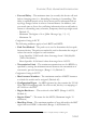
Basic Configuration of Global Settings
• Spanning Tree State – Enables/disables STA on this switch. (Default:
Enabled)
• Spanning Tree Backup Root – Automatically lowers the switch’s
bridge priority by 4096 if it loses contact with the current root device. To
succeed, the switch must have a direct connection to current root bridge,
and its adjusted bridge priority must be higher (i.e., a numerically lower
value) than all the other bridges in the spanning tree. (Default: Disabled)
• Spanning Tree Type – Specifies the type of spanning tree used on this
switch:
- STP: Spanning Tree Protocol (IEEE 802.1D; i.e., when this option is
selected, the switch will use RSTP set to STP forced compatibility
mode)