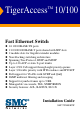
TigerAccess™ 10/100 Fast Ethernet Switch ◆ ◆ ◆ ◆ ◆ ◆ ◆ ◆ ◆ ◆ ◆ ◆ ◆ 24 10/100BASE-TX ports 2 10/100/1000BASE-T ports shared with SFP slots 2 module slots for Gigabit extender modules Non-blocking switching architecture Spanning Tree Protocol, RSTP and MSTP Up to 12 LACP or static 8-port trunks Layer 2/3/4 CoS support through eight priority queues Layer 3/4 traffic priority with IP Precedence and IP DSCP Full support for VLANs with GVRP and QinQ IGMP multicast filtering and snooping Support for jumbo frames
TigerAccess™ 10/100 Installation Guide From SMC’s Tiger line of feature-rich workgroup LAN solutions 38 Tesla Irvine, CA 92618 Phone: (949) 679-8000 January 2007 Pub.
Information furnished by SMC Networks, Inc. (SMC) is believed to be accurate and reliable. However, no responsibility is assumed by SMC for its use, nor for any infringements of patents or other rights of third parties which may result from its use. No license is granted by implication or otherwise under any patent or patent rights of SMC. SMC reserves the right to change specifications at any time without notice. Copyright © 2007 by SMC Networks, Inc. 38 Tesla Irvine, CA 92618 All rights reserved.
LIMITED WARRANTY Limited Warranty Statement: SMC Networks, Inc. (“SMC”) warrants its products to be free from defects in workmanship and materials, under normal use and service, for the applicable warranty term. All SMC products carry a standard 90-day limited warranty from the date of purchase from SMC or its Authorized Reseller. SMC may, at its own discretion, repair or replace any product not operating as warranted with a similar or functionally equivalent product, during the applicable warranty term.
WARRANTIES EXCLUSIVE: IF AN SMC PRODUCT DOES NOT OPERATE AS WARRANTED ABOVE, CUSTOMER’S SOLE REMEDY SHALL BE REPAIR OR REPLACEMENT OF THE PRODUCT IN QUESTION, AT SMC’S OPTION. THE FOREGOING WARRANTIES AND REMEDIES ARE EXCLUSIVE AND ARE IN LIEU OF ALL OTHER WARRANTIES OR CONDITIONS, EXPRESS OR IMPLIED, EITHER IN FACT OR BY OPERATION OF LAW, STATUTORY OR OTHERWISE, INCLUDING WARRANTIES OR CONDITIONS OF MERCHANTABILITY AND FITNESS FOR A PARTICULAR PURPOSE.
COMPLIANCES FCC - Class A This equipment has been tested and found to comply with the limits for a Class A digital device, pursuant to part 15 of the FCC Rules. These limits are designed to provide reasonable protection against harmful interference when the equipment is operated in a commercial environment. This equipment generates, uses, and can radiate radio frequency energy and, if not installed and used in accordance with the instruction manual, may cause harmful interference to radio communications.
COMPLIANCES CE Mark Declaration of Conformance for EMI and Safety (EEC) SMC contact for these products in Europe is: SMC Networks Europe, Edificio Conata II, Calle Fructuós Gelabert 6-8, 2o, 4a, 08970 - Sant Joan Despí, Barcelona, Spain.
COMPLIANCES Australia AS/NZS 3548 (1995) - Class A N11846 SMC contact for products in Australia is: SMC Communications Pty. Ltd. Suite 18, 12 Tryon Road, Lindfield NSW2070, Phone: 61-2-94160437 Fax: 61-2-94160474 Safety Compliance Warning: Fiber Optic Port Safety CLASS I LASER DEVICE When using a fiber optic port, never look at the transmit laser while it is powered on. Also, never look directly at the fiber TX port and fiber cable ends when they are powered on.
COMPLIANCES Power Cord Safety Please read the following safety information carefully before installing the switch: Warning: Installation and removal of the unit must be carried out by qualified personnel only. • The unit must be connected to an earthed (grounded) outlet to comply with international safety standards. • Do not connect the unit to an A.C. outlet (power supply) without an earth (ground) connection.
COMPLIANCES Power Cord Set (Continued) Europe The supply plug must comply with CEE7/7 (“SCHUKO”). The mains cord must be or marked and be of type HO3VVF3GO.75 (minimum). IEC-320 receptacle. Veuillez lire à fond l'information de la sécurité suivante avant d'installer le Switch: AVERTISSEMENT: L’installation et la dépose de ce groupe doivent être confiés à un personnel qualifié.
COMPLIANCES Cordon électrique - Il doit être agréé dans le pays d’utilisation (Continued) Danemark: La prise mâle d’alimentation doit respecter la section 107-2 D1 de la norme DK2 1a ou DK2 5a. Suisse: La prise mâle d’alimentation doit respecter la norme SEV/ASE 1011. Europe La prise secteur doit être conforme aux normes CEE 7/7 (“SCHUKO”) LE cordon secteur doit porter la mention ou et doit être de type HO3VVF3GO.75 (minimum).
COMPLIANCES Warnings and Cautionary Messages Warning: This product does not contain any serviceable user parts. Warning: Installation and removal of the unit must be carried out by qualified personnel only. Warning: When connecting this device to a power outlet, connect the field ground lead on the tri-pole power plug to a valid earth ground line to prevent electrical hazards. Warning: This switch uses lasers to transmit signals over fiber optic cable.
COMPLIANCES Environmental Statement The manufacturer of this product endeavours to sustain an environmentally-friendly policy throughout the entire production process. This is achieved though the following means: • • • • • • Adherence to national legislation and regulations on environmental production standards. Conservation of operational resources. Waste reduction and safe disposal of all harmful un-recyclable by-products. Recycling of all reusable waste content.
TABLE OF CONTENTS 1 About the TigerAccess Switch . . . . . . . . . . . . . . . . . . . 1-1 Overview . . . . . . . . . . . . . . . . . . . . . . . . . . . . . . . . . . . . . . . . . . . . . . . . . 1-1 Switch Architecture . . . . . . . . . . . . . . . . . . . . . . . . . . . . . . . . . . . 1-2 Network Management Options . . . . . . . . . . . . . . . . . . . . . . . . . . 1-2 Description of Hardware . . . . . . . . . . . . . . . . . . . . . . . . . . . . . . . . . . . . .
TABLE OF CONTENTS Optional Rack-Mounting Equipment . . . . . . . . . . . . . . . . . . . . . 3-3 Mounting . . . . . . . . . . . . . . . . . . . . . . . . . . . . . . . . . . . . . . . . . . . . . . . . . 3-4 Rack Mounting . . . . . . . . . . . . . . . . . . . . . . . . . . . . . . . . . . . . . . . 3-4 Desktop or Shelf Mounting . . . . . . . . . . . . . . . . . . . . . . . . . . . . . 3-6 Installing an Optional Module into the Switch . . . . . . . . . . . . . . . . . . . .
TABLE OF CONTENTS APPENDICES: A Troubleshooting . . . . . . . . . . . . . . . . . . . . . . . . . . . . . .A-1 Diagnosing Switch Indicators . . . . . . . . . . . . . . . . . . . . . . . . . . . . . . . . . A-1 Power and Cooling Problems . . . . . . . . . . . . . . . . . . . . . . . . . . . . . . . . . A-3 Installation . . . . . . . . . . . . . . . . . . . . . . . . . . . . . . . . . . . . . . . . . . . . . . . . A-3 In-Band Access . . . . . . . . . . . . . . . . . . . . . . . . . . . . . . . . . . . . . .
TABLE OF CONTENTS E Ordering Information . . . . . . . . . . . . . . . . . . . . . . . . . .
TABLES Table 1-1 Table 1-2 Table 3-1 Table 3-2 Table 4-1 Table 4-2 Table 4-5 Table 4-6 Table 4-3 Table 4-4 Table A-1 Table B-1 Table B-2 Table E-1 Optional SFP Transceivers . . . . . . . . . . . . . . . . . . . . . . . . . . . . 1-4 Port and System Status LEDs . . . . . . . . . . . . . . . . . . . . . . . . . 1-6 Serial Cable Wiring . . . . . . . . . . . . . . . . . . . . . . . . . . . . . . . . . 3-14 Alarm Cable Wiring . . . . . . . . . . . . . . . . . . . . . . . . . . . . . . . .
FIGURES Figure 1-1 Figure 1-2 Figure 1-3 Figure 1-4 Figure 1-5 Figure 2-1 Figure 2-2 Figure 2-3 Figure 2-4 Figure 3-1 Figure 3-2 Figure 3-3 Figure 3-4 Figure 3-5 Figure 3-6 Figure 3-7 Figure 3-8 Figure 3-9 Figure 3-10 Figure 3-11 Figure 4-1 Figure 4-2 Figure 4-3 Figure B-1 Figure B-2 Figure B-3 Figure D-1 Figure D-2 Front Panel . . . . . . . . . . . . . . . . . . . . . . . . . . . . . . . . . . . . 1-2 Port and System LEDs . . . . . . . . . . . . . . . . . . . . . . . . . . . 1-5 Fan Tray . . . . . . . . .
CHAPTER 1 ABOUT THE TIGERACCESS SWITCH Overview The TigerAccess 10/100 is an intelligent Layer 2 switch with 24 10/100BASE-TX ports for subscriber access to the data network, two Gigabit Ethernet combination ports* for uplink traffic. The uplink ports are implemented as 10/100/1000BASE-T ports shared with SFP transceiver slots (see Figure 1-1, Ports 27-28).
ABOUT THE TIGERACCESS SWITCH System and Port indicators 100BASE-TX Subscriber Ports Ground and Power Connection Points Power Trays 8.7A Mgmt Mgmt 8.7A Alarm Connector Gigabit Combo Ports Fan Tray GPON/GEPON Module Slot (located behind the Gigabit combo Console Port Gigabit Combo Module Slots module slots and mounting tray) (for 1000BASE-T/SFP Ports) Management Port Figure 1-1 Front Panel Switch Architecture This switch employs a wire-speed, non-blocking switching fabric.
DESCRIPTION OF HARDWARE connection (in-band) using Telnet, the on-board web agent, or SNMP-based network management software. The management port (RJ-45) provides a dedicated management channel that operates outside of the data transport network. This makes it possible to re-configure or troubleshoot the switch over either a local or remote connection to the management port when access via the data channel is not possible or deemed insecure.
ABOUT THE TIGERACCESS SWITCH This port supports auto-negotiation, so the optimum transmission mode (half or full duplex) and data rate (10 or 100 Mbps) can be selected automatically, if this feature is also supported by the attached device. However, note that the interface connection parameters of this port cannot be configured.
DESCRIPTION OF HARDWARE Alarm Interface Port The DB-15 alarm port on the switch’s front panel can be used to provide alarm, service port, and BITS clock reference interfaces. The switch supports two sets of alarm relay contacts (major and minor), and 4 external customer site alarm inputs. It also provides an alarm cutoff button (labeled ACO). Refer to “Connecting to the Alarm Port” on page 3-15 for a description of the pin assignments used to connect to the alarm port.
ABOUT THE TIGERACCESS SWITCH Table 1-2 Port and System Status LEDs LED Condition Status Major Red Indicates presence within the system of one or more major traffic-affecting system alarm(s) that are not masked by the alarm filter. Minor Amber Indicates presence within the system of one or more minor traffic-affecting system alarm(s) that are not masked by the alarm filter. Fan Fail Red Indicates failure of one or more fans. Diag Flashing Green System self-diagnostic test in progress.
DESCRIPTION OF HARDWARE Fan Tray A removable fan tray on the right side of the front panel contains three fans that provide cooling for the chassis.
ABOUT THE TIGERACCESS SWITCH Power Modules This switch provides two power module options: -48 VDC and universal AC. For specifications on the power conversion modules and external input power requirements, see “Power Supply” on page C-2.
OPTIONAL MEDIA EXTENDER MODULE Optional Media Extender Module 1000BASE Combo Module Figure 1-5 Single-Port 1000BASE-T/SFP Combo Module The 1000BASE-T RJ-45 port and SFP slot on this module share the same internal interface. If an SFP transceiver (purchased separately) is installed in a slot and has a valid link, the associated RJ-45 port is disabled and cannot be used. The switch can also be configured to force the use of an RJ-45 port or SFP slot, as required.
ABOUT THE TIGERACCESS SWITCH Features and Benefits Connectivity • 24 100BASE-TX ports for 10 or 100 Mbps Ethernet connections to subscribers. • 2 1000BASE-T ports provide 4 Gbps of aggregate bandwidth for network uplink. • Auto-negotiation enables each RJ-45 data port and uplink port to automatically select the optimum communication mode (half or full duplex) if this feature is supported by the attached device; otherwise the port can be configured manually.
FEATURES AND BENEFITS • Switching table with a total of 16K MAC address entries and 1K static addresses. • Provides store-and-forward switching for intra-VLAN traffic. • Supports wire-speed switching. • Supports flow control, using back pressure for half duplex and IEEE 802.3x for full duplex.
ABOUT THE TIGERACCESS SWITCH 1-12
CHAPTER 2 NETWORK PLANNING Introduction to Switching A network switch allows simultaneous transmission of multiple packets via non-crossbar switching. This means that it can partition a network more efficiently than bridges or routers. These switches have, therefore, been recognized as one of the most important building blocks for today’s networking technology.
NETWORK PLANNING Collapsed Backbone This switch is an excellent choice for mixed Ethernet, Fast Ethernet, and Gigabit Ethernet installations where significant growth is expected in the near future. In a basic stand-alone configuration, it can provide direct full-duplex connections for up to 28 workstations or servers. You can easily build on this basic configuration, adding direct full-duplex connections to workstations or servers.
APPLICATION EXAMPLES Network Aggregation Plan With 28 parallel bridging ports (i.e., distinct collision domains), this switch can collapse a complex network down into a single efficient bridged node, increasing overall bandwidth and throughput. In the figure below, the 10/100/1000BASE-T ports are providing 1 Gbps connectivity through cascaded switches. In addition, the switches are also connecting several servers at 1 Gbps. 10/100/1000 Switch 8.7A Mgmt Mgmt 8.
NETWORK PLANNING Remote Connections with Fiber Cable Fiber optic technology allows for longer cabling than any other media type. A 1000BASE-SX (MMF) link can connect to a site up to 550 meters away, a 1000BASE-LX (SMF) link up to 10 km, and a 1000BASE-ZX link up to 70 km. This allows a switch to serve as a collapsed backbone, providing direct connectivity for a widespread LAN. A 1000BASE-SX SFP transceiver can be used for a high-speed connection between floors in the same building.
APPLICATION EXAMPLES Making VLAN Connections These switches support VLANs which can be used to organize any group of network nodes into separate broadcast domains. VLANs confine broadcast traffic to the originating group, and can eliminate broadcast storms in large networks. This provides a more secure and cleaner network environment. VLANs can be based on untagged port groups, or traffic can be explicitly tagged to identify the VLAN group to which it belongs.
NETWORK PLANNING Application Notes 1. Full-duplex operation only applies to point-to-point access (such as when a switch is attached to a workstation, server or another switch). When the switch is connected to a hub, both devices must operate in half-duplex mode. 2. To interconnect distinct VLANs or IP subnets, you can attach the switch to a standard Layer 3 router. For network applications that require routing between dissimilar network types, attach the switch to a multi-protocol router. 3.
CHAPTER 3 INSTALLING THE SWITCH Selecting a Site TigerAccess 10/100 units can be mounted in a standard 19-inch equipment rack or on a flat surface. Be sure to follow the guidelines below when choosing a location. • The site should: - restrict access to authorized service personnel in accordance with IEC 60950-1. A restricted access location is one where access is secure and limited to service personnel who have a special key, or other means of security.
INSTALLING THE SWITCH is recommended. This switch provides two power module options: -48 VDC and universal AC. Verify that the external power requirements for the selected option can be met as listed under “Power Supply” on page C-2. Ethernet Cabling To ensure proper operation when installing switches into a network, make sure that the current cables are suitable for 10BASE-T, 100BASE-TX or 1000BASE-T operation.
EQUIPMENT CHECKLIST Equipment Checklist After unpacking the TigerAccess 10/100 unit, check the contents to be sure you have received all the components. Then, before beginning the installation, be sure you have all other necessary installation equipment.
INSTALLING THE SWITCH Mounting A TigerAccess 10/100 unit can be mounted in a standard 19-inch equipment rack or on a desktop or shelf. Mounting instructions for each type of site follow. Rack Mounting Before rack mounting the switch, pay particular attention to the following factors: • Temperature: Since the temperature within a rack assembly may be higher than the ambient room temperature, check that the rack-environment temperature is within the specified operating temperature range. (See page C-2.
MOUNTING 2. Mount the device in the rack, using four rack-mounting screws (not provided). Mgmt Figure 3-3 Installing the Switch in a Rack 3. If installing a single switch only, turn to Grounding the Chassis at the end of this chapter. 4. If installing multiple switches, mount them in the rack, one below the other, in any order.
INSTALLING THE SWITCH Desktop or Shelf Mounting 1. Attach the four adhesive feet to the bottom of the first switch. Mgm t Mgm t 8.7A 8.7A Figure 3-4 Attaching the Adhesive Feet 2. Set the device on a flat surface near an external power source, making sure there are at least two inches of space on all sides for proper air flow. 3. If installing a single switch only, go to Grounding the Chassis at the end of this chapter. 4. If installing multiple switches, attach four adhesive feet to each one.
INSTALLING AN OPTIONAL MODULE INTO THE SWITCH Installing an Optional Module into the Switch Mgmt Figure 3-5 Installing an Optional Module Note: The slide-in modules are hot-swappable, you do not need to power off the switch before installing or removing a module. To install an optional module into the switch, do the following: 1. Remove the blank metal plate (or a previously installed module) from the appropriate slot by removing the two screws with a flat-head screwdriver. 2.
INSTALLING THE SWITCH 5. If you are sure the module is properly mated with the connector, tighten the retainer screws to secure the module in the slot. 6. To confirm that the module is correctly installed and ready to use, connect an active device to the module, and verify that the corresponding port indicator on the switch’s front panel turns green to show that there is a valid link.
GROUNDING THE CHASSIS Notes: 1. SFP transceivers are hot-swappable. The switch does not need to be powered off before installing or removing a transceiver. However, always first disconnect the network cable before removing a transceiver. 2. SFP transceivers are not provided in the switch package. Grounding the Chassis Before powering on the switch, ground the switch to earth as described below. 1.
INSTALLING THE SWITCH Connecting to a Power Source This switch supports both AC and DC power conversion modules. Connecting DC Power When a -48 VDC power conversion module is installed in the switch, an external DC power supply must be connected to the DC power connection on the left side of the front panel. Warning: Before wiring the DC plug or connecting power to the switch, ensure that power to the feed lines is turned off at the supply circuit breaker or disconnected from the power bus. Notes: 1.
CONNECTING TO A POWER SOURCE To connect the switch to a power source: 1. First verify that the external DC power supply can provide -36 to -72 VDC, 4 A minimum for the -48 VDC power conversion module. 2. Prepare two wires for each power source to be used (A or B). Use 10 to 24 AWG stranded copper wire. Make sure these wires are not plugged into the power source. 3. Use a wire stripper to carefully strip about a half an inch of the outer insulation off the end of each wire, exposing the copper core. 4.
INSTALLING THE SWITCH -48VDC/Ground (Source A) Return/24VDC (Source A) -48VDC/Ground (Source B) Return/24VDC (Source B) Figure 3-7 DC Plug Connections 7. Push each wire about half an inch into the opening on the plug, and tighten down the clamp screw securely. You should not be able to pull on the wire and dislodge it. 8. Insert the power plug in the power receptacle on the left side of the front panel. 9. At the power source, turn on the power for the feed lines or power bus. 10.
CONNECTING TO A POWER SOURCE Connecting AC Power When a universal AC power module is installed in the switch, external AC power must be supplied to the module. To connect the switch to a power source: 1. First verify that the external AC power supply can provide 100 to 240 VAC, 50-60 Hz, 2 A minimum. 2. Plug the power cable into a grounded, 3-pin, AC power source. Note: For international use, you may need to change the AC line cord.
INSTALLING THE SWITCH 5. If you have installed both a primary and redundant power conversion modules, verify that the LEDs on both modules are lit as indicated in the preceding step. Connecting to the Console Port The RJ-45 serial port on the switch’s front panel is used to connect to the switch for out-of-band console configuration. The on-board configuration program can be accessed from a terminal or a PC running a terminal emulation program.
CONNECTING TO THE ALARM PORT The serial port’s configuration requirements are as follows: • Default Baud rate—9,600 bps • Character Size—8 Characters • Parity—None • Stop bit—One • Data bits—8 • Flow control—none Connecting to the Alarm Port The DB-15 alarm port on the switch’s front panel is used to provide alarm, service port, and BITS clock reference interfaces. The switch supports two sets of alarm relay contacts (major and minor), and 4 external customer site alarm inputs.
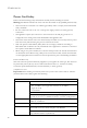
INSTALLING THE SWITCH Wiring Map for Alarm Cable The signals include relay contacts for major and minor system alarms, and external alarm inputs. Table 3-2 Alarm Cable Wiring Switch’s Alarm Port Function 1 (MJR_ALARM_CNTR) Common contact for major alarm relay. 2 (MNR_ALARM_CNTR) Common contact for minor alarm relay. 3 (ALARM_IN3_EXT_P*) External alarm input 3 (external relay dry contact closure to pin 13). 4 (ALARM_IN4_EXT_P) External alarm input 4 (external relay dry contact closure to pin 8).
CONNECTING TO THE ALARM PORT The following figure shows the pinout information for the DB-15 ALARM connector on the front panel. Alarm Connector 1 NC 11 COM 6 NO Major Alarm 2 NC 12 COM 7 NO 9 10 3 4 External Alarm Input 1 External Alarm Input 2 External Alarm Input 3 External Alarm Input 4 Minor Alarm To backplane via internal signal converter circuits. External input uses dry relay contact to pins 14, 15, 13 and 8 for grounding. For active alarm, the relay is closed.
INSTALLING THE SWITCH 3-18
CHAPTER 4 MAKING NETWORK CONNECTIONS Connecting Network Devices The TigerAccess 10/100 switch is designed to interconnect multiple segments (or collision domains). It can be connected to network cards in PCs and servers, as well as to hubs, switches or routers. It may also be connected to devices using optional SFP transceivers. Twisted-Pair Devices Each device requires an unshielded twisted-pair (UTP) cable with RJ-45 connectors at both ends.
MAKING NETWORK CONNECTIONS Caution: Do not plug a phone jack connector into an RJ-45 port. This will damage the switch. Use only twisted-pair cables with RJ-45 connectors that conform to FCC standards. Connecting to PCs, Servers, Hubs and Switches 1. Attach one end of a twisted-pair cable segment to the device’s RJ-45 connector. Figure 4-1 Making Twisted-Pair Connections 2.
TWISTED-PAIR DEVICES Network Wiring Connections Today, the punch-down block is an integral part of many of the newer equipment racks. It is actually part of the patch panel. Instructions for making connections in the wiring closet with this type of equipment follows. 1. Attach one end of a patch cable to an available port on the switch, and the other end to the patch panel. 2.
MAKING NETWORK CONNECTIONS Fiber Optic SFP Devices An optional Gigabit SFP transceiver (1000BASE-SX, 1000BASE-LX or 1000BASE-ZX) can be used for a backbone connection between switches, or for connecting to a high-speed server. Each single-mode fiber port requires 9/125 micron single-mode fiber optic cable with an LC connector at both ends. Each multimode fiber optic port requires 50/125 or 62.5/125 micron multimode fiber optic cabling with an LC connector at both ends.
FIBER OPTIC SFP DEVICES will impair the quality of the light transmitted through the cable and lead to degraded performance on the port. 3. Connect one end of the cable to the LC port on the switch and the other end to the LC port on the other device. Since LC connectors are keyed, the cable can be attached in only one orientation. Mgm t Figure 4-3 Making Connections to SFP Transceivers 4.
MAKING NETWORK CONNECTIONS Connectivity Rules When adding hubs (repeaters) to your network, please follow the connectivity rules listed in the manuals for these products. However, note that because switches break up the path for connected devices into separate collision domains, you should not include the switch or connected cabling in your calculations for cascade length involving other devices.
CONNECTIVITY RULES Table 4-3 Maximum 1000BASE-LX Gigabit Ethernet Cable Length Fiber Size Fiber Bandwidth Maximum Cable Length 9/125 micron N/A single-mode duplex fiber 2 m - 10 km (7 ft - 6.2 miles) Connector LC Table 4-4 Maximum 1000BASE-ZX Gigabit Ethernet Cable Length Fiber Size Fiber Bandwidth Maximum Cable Length Connector 9/125 micron single-mode fiber N/A LC 70* - 100 km (43.5 - 62.
MAKING NETWORK CONNECTIONS Cable Labeling and Connection Records When planning a network installation, it is essential to label the opposing ends of cables and to record where each cable is connected. Doing so will enable you to easily locate inter-connected devices, isolate faults and change your topology without need for unnecessary time consumption. To best manage the physical implementations of your network, follow these guidelines: 4-8 • Clearly label the opposing ends of each cable.
APPENDIX A TROUBLESHOOTING Diagnosing Switch Indicators This switch can be easily monitored through panel indicators to identify problems. The table below describes common problems you may encounter and possible solutions. Table A-1 Diagnosing Switch Indicators Symptom Possible Cause Action Power Module LED is off Power outlet, power cord, or power module may be defective. • If using a DC power conversion module, check the connections between the switch and the external DC power supply.
TROUBLESHOOTING Table A-1 Diagnosing Switch Indicators (Continued) Symptom Possible Cause Action Link LED is Off Network cable or Ethernet device attached to this port may be defective. • Verify that the switch and attached device are powered on. • Be sure the cable is plugged into both the switch and corresponding device. • Verify that the proper cable type is used and its length does not exceed specified limits. • Check the adapter on the attached device and cable connections for possible defects.
POWER AND COOLING PROBLEMS Power and Cooling Problems If the power indicator does not turn on when the power cord is plugged in, you may have a problem with the power outlet, power cord, or internal power supply. However, if the unit powers off after running for a while, check for loose power connections, power losses or surges at the power outlet, and verify that the fans on the unit are unobstructed and running prior to shutdown.
TROUBLESHOOTING A-4
APPENDIX B CABLES Twisted-Pair Cable and Pin Assignments For 10/100BASE-TX connections, the twisted-pair cable must have two pairs of wires. For 1000BASE-T connections the twisted-pair cable must have four pairs of wires. Each wire pair is identified by two different colors. For example, one wire might be green and the other, green with white stripes. Also, an RJ-45 connector must be attached to both ends of the cable. Caution: DO NOT plug a phone jack connector into any RJ-45 port.
CABLES 10BASE-T/100BASE-TX Pin Assignments Use unshielded twisted-pair (UTP) or shielded twisted-pair (STP) cable for RJ-45 connections: 100-ohm Category 3, 4 or 5 cable for 10 Mbps connections or 100-ohm Category 5 cable for 100 Mbps connections. Also be sure that the length of any twisted-pair connection does not exceed 100 meters (328 feet).
TWISTED-PAIR CABLE AND PIN ASSIGNMENTS Straight-Through Wiring If the twisted-pair cable is to join two ports and only one of the ports has an internal crossover (MDI-X), the two pairs of wires must be straight-through. (When auto-negotiation is enabled for any RJ-45 port on these switches, you can use either straight-through or crossover cable to connect to any device type.) You must connect all four wire pairs as shown in the following diagram to support Gigabit Ethernet connections.
CABLES Crossover Wiring If the twisted-pair cable is to join two ports and either both ports are labeled with an “X” (MDI-X) or neither port is labeled with an “X” (MDI), a crossover must be implemented in the wiring. (When auto-negotiation is enabled for any RJ-45 port on these switches, you can use either straight-through or crossover cable to connect to any device type.) You must connect all four wire pairs as shown in the following diagram to support Gigabit Ethernet connections.
TWISTED-PAIR CABLE AND PIN ASSIGNMENTS 1000BASE-T Pin Assignments All 1000BASE-T ports support automatic MDI/MDI-X operation, so you can use straight-through cables for all network connections to PCs or servers, or to other switches or hubs. The table below shows the 1000BASE-T MDI and MDI-X port pinouts. These ports require that all four pairs of wires be connected. Note that for 1000BASE-T operation, all four pairs of wires are used for both transmit and receive.
CABLES 1000BASE-T Cable Requirements All Category 5 UTP cables that are used for 100BASE-TX connections should also work for 1000BASE-T, providing that all four wire pairs are connected. However, it is recommended that for all critical connections, or any new cable installations, Category 5e (enhanced Category 5) or Category 6 cable should be used. The Category 5e specification includes test parameters that are only recommendations for Category 5.
FIBER STANDARDS Fiber Standards The current TIA (Telecommunications Industry Association) 568-A specification on optical fiber cabling consists of one recognized cable type for horizontal subsystems and two cable types for backbone subsystems. Horizontal 62.5/125 micron multimode (two fibers per outlet). Backbone 62.5/125 micron multimode or single mode. TIA 568-B will allow the use of 50/125 micron multimode optical fiber in both the horizontal and backbone in addition to the types listed above.
CABLES B-8
APPENDIX C SPECIFICATIONS Physical Characteristics Ports 24 Fast Ethernet subscriber ports (RJ-45) 2 Gigabit Ethernet combination uplink ports (RJ-45/SFP) 2 Gigabit Ethernet extender module slots for uplink (RJ-45/SFP) 1 Fast Ethernet management port (RJ-45) Network Interface Ports 1-24: RJ-45 connector, auto-negotiation, auto MDI/X 10BASE-T: RJ-45 (100-ohm, UTP cable; Category 3 or better) 100BASE-TX: RJ-45 (100-ohm, UTP cable; Category 5 or better) 1000BASE-T: RJ-45 (100-ohm, UTP or STP cable; Category 5,
PHYSICAL CHARACTERISTICS Aggregate Bandwidth 12.8 Gbps Switching Database 8K MAC address entries, 1K static MAC addresses; 64 multicast groups LEDs System: Power Module (-48/+12 VDC, AC/+12VDC), Alarm (Major, Minor, Fan Fail), Diagnostics Port: Status (link, activity) Weight 1.59 kg (3.5 lbs) Size 44.0 x 41.5 x 6.7 cm (17.3 x 16.3 x 2.6 in.
SPECIFICATIONS Maximum Current 1.20 A @ -38 VDC (with two expansion modules) 0.60 A @ -75 VDC (with two expansion modules) 0.59 A @ 110 VAC (with two expansion modules) 0.36 A @ 240 VAC (with two expansion modules) Switch Features Forwarding Mode Store-and-forward Throughput Wire speed Flow Control Full Duplex: IEEE 802.
STANDARDS Standards IEEE 802.3-2005 Ethernet, Fast Ethernet, Gigabit Ethernet Link Aggregation Control Protocol (LACP) Full-duplex flow control (ISO/IEC 8802-3) IEEE 802.1D Spanning Tree Protocol IEEE 802.1w Rapid Spanning Tree Protocol IEEE 802.1s Multiple Spanning Tree Protocol IEEE 802.1p Priority Tags IEEE 802.1Q Virtual LAN IEEE 802.1v Protocol-based VLANs IEEE 802.
SPECIFICATIONS Safety CSA/CUS (CSA 22.2. NO 60950-1 & UL60950-1) TÜV/GS (EN60950-1) CB (IEC60950-1) Extender Modules Gigabit Extender Module (RJ-45/SFP) Ports 1 10/100/1000BASE-T RJ-45/SFP combo port Communication Speed 1 Gbps Communication Mode Full duplex Network Interface RJ-45/SFP slot Standards IEEE 802.
EXTENDER MODULES C-6
APPENDIX D GERMAN INSTRUCTIONS Eine Site Auswählen (Selecting a Site) Die Schalter können in ein Standard-19-Zoll-Ausrüstungsgestell oder auf eine flache Ebene montiert werden. Zum Auswählen eines Standortes beachten Sie bitte die nachstehenden Richtlinien.
GERMAN INSTRUCTIONS • Sicherstellen, dass das Gerat an eine separate Stromquelle mit Erdanschlus mit einer Netzspannung von 100 bis 240 V AC (Wechselstromspannung), 50 bis 60 Hz, und innerhalb in einem Abstand von 2,44 m (8 Fus) zu jedem Gerat installiert wird und on einem separaten Trennschalter bzw. Leistungsschalter mit Strom versorgt wird. Fur alle Gerate wird empfohlen, einen Filter oder einen Überspannungsschutz zu verwenden.
DAS ERDEN DES GEHÄUSES (GROUNDING THE CHASSIS) So montieren Sie Geräte an ein Rack: 1. Befestigen Sie die Metallwinkel mit den im Metallwinkel-Montageset erhältlichen Schrauben an dem Gerät. 2. Befestigen Sie das Gerät mit vier Rackmontageschrauben (nicht beigelegt) an dem Rack. 3. Wenn Sie nur einen Switch installieren, dann springen Sie bitte über zu “Verbinden mit einer Stromquelle” auf Seite 3-9 am Ende dieses Kapitels. 4.
GERMAN INSTRUCTIONS 5. Dann schließen Sie das Erdungskabel an den Erdungspunkt des Racks an. Vorsicht: Die Erdungsverbindungen dürfen nicht entfernt werden, es sei denn, alle Verbindungen zu den Stromquellen sind abgezogen. Anschluss an eine Stromquelle (Connecting to a Power Source) Dieser Switch unterstützt sowohl Gleichstrom- als auch Wechselstrom-Umwandlungsmodule.
ANSCHLUSS AN EINE STROMQUELLE (CONNECTING TO A POWER SOURCE) Plug Connections” auf Seite 3-8 beschrieben sind, erfüllt sind. Die Drähte sollten auch gemäß der örtlichen Normen gefärbt sein, um sicherzustellen, dass die Stromeingangskabel und die Erdungsdrähte leicht unterschieden werden können. 4. Wenn Sie die zwei Stromwandlungsmodule benutzen, können Sie sowohl Wechsel- als auch Gleichstrommodule verwenden – beide Wechstelstrom, beide Gleichstrom oder ein Wechselstrom und ein Gleichstrom.
GERMAN INSTRUCTIONS RETA/B (Return) Leitungen für die Stromquellen A bzw. B benutzt. Benutzen Sie einen Flachkopfschraubendreher, um die Schrauben des Steckers zu lösen und öffnen Sie die Drahtklammern. 6. Fügen Sie die Verbindungsleitungen in die Öffnungen, wie im unteren Bild gezeigt, ein. Jede Leitung, welche in den Stecker eingefügt wird, muß der Leitung, die an die Stromquelle angeschlossen ist, entsprechen.
ANSCHLUSS AN EINE STROMQUELLE (CONNECTING TO A POWER SOURCE) Stromschalter auf der Vorderseite des Stromwandlungsmodule auf AN (mit “–” markiert). 11. Überprüfen Sie die Anzeigen auf den Stromwandlungsmodulen, wenn der Schalter angeschaltet ist, um sicherzugehen, dass die -48V bzw. die den externen Stromstatus anzeigt, an ist, und dass auch die +12V LED, die den internen Stromstatus anzeigt, an ist.
GERMAN INSTRUCTIONS Figure D-2 Wechselstromanschluss 4. Wenn der Switch angeschaltet ist, überprüfen Sie die Anzeigen des Strommoduls, um sicherzugehen, dass sowohl die Wechselstrom LED, die den externen Stromstatus anzeigt, als auch die +12V LED, die die interne Stromwandlung anzeigt, leuchtet. Wenn nicht, überprüfen Sie noch einmal die Stromquelle und die Stromverbindungen an der Stromquelle und am Stromwandlungsmodul. 5.
APPENDIX E ORDERING INFORMATION Table E-1 TigerAccess 10/100 Products and Accessories Product Number Description SMC7824M/ESW 24-Port Fast Ethernet Switch with 2 combo Gigabit Ethernet uplink ports (RJ-45/SFP), 2 Gigabit Ethernet extender module slots (RJ-45/SFP), and 1 dedicated Gigabit Ethernet management port (RJ-45) SMCBGSLCX1 Single-port 1000BASE-SX Small Form Pluggable (SFP) mini-GBIC transceiver SMCBGLLCX1 Single-port 1000BASE-LX Small Form Pluggable (SFP) mini-GBIC transceiver SMCBGZLCX1 Si
ORDERING INFORMATION E-2
GLOSSARY 10BASE-T IEEE 802.3 specification for 10 Mbps Ethernet over two pairs of Category 3, 4, or 5 UTP cable. 100BASE-TX IEEE 802.3u specification for 100 Mbps Fast Ethernet over two pairs of Category 5 or better UTP cable. 1000BASE-LX IEEE 802.3z specification for Gigabit Ethernet over two strands of 50/ 125, 62.5/125 or 9/125 micron core fiber cable. 1000BASE-SX IEEE 802.3z specification for Gigabit Ethernet over two strands of 50/125 or 62.5/125 micron core fiber cable. 1000BASE-T IEEE 802.
GLOSSARY Bandwidth The difference between the highest and lowest frequencies available for network signals. Also synonymous with wire speed, the actual speed of the data transmission along the cable. Collision A condition in which packets transmitted over the cable interfere with each other. Their interference makes both signals unintelligible. Collision Domain Single CSMA/CD LAN segment.
GLOSSARY Full Duplex Transmission method that allows two network devices to transmit and receive concurrently, effectively doubling the bandwidth of that link. Gigabit Ethernet A 1000 Mbps network communication system based on Ethernet and the CSMA/CD access method. IEEE Institute of Electrical and Electronic Engineers. IEEE 802.3 Defines carrier sense multiple access with collision detection (CSMA/CD) access method and physical layer specifications. IEEE 802.
GLOSSARY Local Area Network (LAN) A group of interconnected computer and support devices. Media Access Control (MAC) A portion of the networking protocol that governs access to the transmission medium, facilitating the exchange of data between network nodes. MIB An acronym for Management Information Base. It is a set of database objects that contains information about the device.
GLOSSARY Transmission Control Protocol/Internet Protocol (TCP/IP) Protocol suite that includes TCP as the primary transport protocol, and IP as the network layer protocol. UTP Unshielded twisted-pair cable. Virtual LAN (VLAN) A Virtual LAN is a collection of network nodes that share the same collision domain regardless of their physical location or connection point in the network.
GLOSSARY Glossary-6
INDEX Numerics buffer size C-1 10 Mbps connectivity rules 4-7 100 Mbps connectivity rules 4-7 1000 Mbps connectivity rules 4-6 1000BASE combo module 1-9 1000BASE-LX fiber cable lengths 4-7 1000BASE-SX fiber cable lengths 4-6 1000BASE-T cable lengths 4-6 pin assignments B-5 ports 1-3 1000BASE-ZX fiber cable lengths 4-7 100BASE-TX cable lengths 4-7 management port 1-3 pin assignments B-2 ports 1-3 10BASE-T cable lengths 4-7 pin assignments B-2 ports 1-3 C A accessories, ordering E-1 adhesive feet, attachi
INDEX fiber cables 4-4 duplex fiber 4-4 multimode 4-4 simplex fiber 4-4 single mode 4-4 full-duplex connectivity 2-1 I IEEE 802.3 Ethernet 1-10 IEEE 802.3u Fast Ethernet 1-10 IEEE 802.
INDEX R RJ-45 port 1-3 connections 4-1 pinouts B-5 rubber foot pads, attaching 3-6 power C-2 standards, IEEE C-4 status LEDs 1-5 surge suppressor, using 3-1 switch architecture 1-2 switching, introduction to 2-1 S T screws for rack mounting 3-3 serial port, management port 1-4 SFP slots 1-4 supported transceivers 1-4 transceiver connections 4-4 single-mode fiber optic cables 4-4 site selelction 3-1 SNMP agent 1-2 specifications compliances C-4 environmental C-2 media extender module C-5 physical C-1 t
INDEX Index-4
FOR TECHNICAL SUPPORT, CALL: From U.S.A. and Canada (24 hours a day, 7 days a week) (800) SMC-4-YOU; (949) 679-8000; Fax: (949) 679-1481 From Europe: Contact details can be found on www.smc-europe.com or www.smc.com INTERNET E-mail addresses: techsupport@smc.com european.techsupport@smc-europe.com Driver updates: http://www.smc.com/index.cfm?action=tech_support_drivers_downloads World Wide Web: http://www.smc.com http://www.smc-europe.com FOR LITERATURE OR ADVERTISING RESPONSE, CALL: U.S.A.