
User's Manual

D
ESCRIPTION
OF
H
ARDWARE
1-5
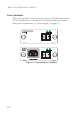
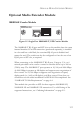
Alarm Interface Port
The DB-15 alarm port on the switch’s front panel can be used to provide
alarm, service port, and BITS clock reference interfaces. The switch
supports two sets of alarm relay contacts (major and minor), and 4 external
customer site alarm inputs. It also provides an alarm cutoff button (labeled
ACO). Refer to “Connecting to the Alarm Port” on page 3-15 for a
description of the pin assignments used to connect to the alarm port.
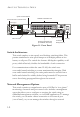
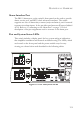
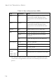
Port and System Status LEDs
This switch includes a display panel for key system and port indications
that simplifies installation and network troubleshooting. The LEDs, which
are located on the front panel and the power module trays for easy
viewing, are shown below and described in the following tables.
Figure 1-2 Port and System LEDs
MgmtMgmt