Copyright Information furnished by SMC Networks, Inc. (SMC) is believed to be accurate and reliable. However, no responsibility is assumed by SMC for its use, nor for any infringements of patents or other rights of third parties which may result from its use. No license is granted by implication or otherwise under any patent or patent rights of SMC. SMC reserves the right to change specifications at any time without notice. The products and programs described in this User Guide are licensed products of SMC.
Compliances FCC - Class B This equipment has been tested and found to comply with the limits for a Class B digital device, pursuant to Part 15 of the FCC Rules. These limits are designed to provide reasonable protection against harmful interference in a residential installation. This equipment generates, uses and can radiate radio frequency energy and, if not installed and used in accordance with instructions, may cause harmful interference to radio communications.
EC Conformance Declaration – Class B SMC contact for these products in Europe is: SMC Networks Europe, Edificio Conata II Calle Fructuos Gelabert 6-8, 2o, 4a 08970 – Sant Joan Despi Barcelona, Spain This equipment complies with the requirements relating to electromagnetic compatibility, EN 55022/A1 Class B, and EN 50082-1.
1 | System Requirements • • • • • Internet access from your local telephone company or Internet Service Provider (ISP) using a DSL modem, cable modem, Dial-Up modem, or ISDN modem A PC using a fixed IP address or dynamic IP address assigned via DHCP, as well as a Gateway server address and DNS server address from your service provider A computer equipped with a 10 Mbps, 100 Mbps, or 10/100 Mbps Fast Ethernet card, or a USB-to-Ethernet converter TCP/IP network protocol installed on each PC that needs to acc
3 | Functions and Features Broadband Modem and NAT Router Connects multiple computers to a broadband (cable or DSL) modem, and/or Ethernet router to access the Internet. 10/100 Mbps Ethernet Interface Provides a 10/100 Base-TX interface to connect to a DSL or cable modem for broadband Internet access. Equipped with a 4/8-port auto-sensing Ethernet switch.
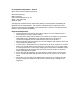
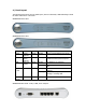
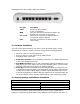
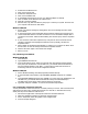
4 | Panel Layout The following figure shows the front panel layout, which is followed by a table describing in detail the status and function of each LED.
SMCBR18VPN Front Panel: 8 LAN, 1 WAN, and 1 COM port Port Type Description 5 VDC Receptor for power adapter: 5 VDC, 2 A (minimum) This is the connection for the Ethernet cable to the Ethernet port on the cable or DSL modem These are the connections for Ethernet cables to your Ethernet enabled computers Serial port (connection for an analog modem or console cable) WAN Port 1–4/8 COM 5 | Hardware Installation The router can be placed anywhere in your office or home.
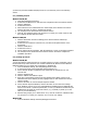
you have not previously installed TCP/IP protocols on your client PCs, refer to the following section. 6.1 | Installing TCP/IP Windows 95/98/Me 1. Click Start/Settings/Control Panel. 2. Double-click the Network icon and select the Configuration tab in the Network window. 3. Click the Add button. 4. Double-click Protocol. 5. Select Microsoft in the manufacturers list. Select TCP/IP in the Network Protocols list. Click the OK button to return to the Network window. 6.
2. 3. 4. 5. 6. 7. 8. 9. Double-click the Network icon. Click on the Protocols tab. Double-click TCP/IP Protocol. Click on the IP Address tab. In the Adapter drop-down list, be sure your Ethernet adapter is selected. Click on “Obtain an IP address from a DHCP server.” Click OK to close the window. Windows may copy files and will then prompt you to restart your system. Click Yes and your computer will shut down and restart. Windows 2000/XP 1.
6.5 | Verifying Your TCP/IP Connection After installing the TCP/IP communication protocols and configuring an IP address in the same network as the Router, use the ping command to check if your computer has successfully connected to the Router. The following example shows how the ping procedure can be executed in an MS-DOS window. First, execute the ping command: ping 192.168.2.1 If a message similar to the following appears: Pinging 192.168.2.1 with 32 bytes of data: Reply from 192.168.2.
7 | Configuring Your Broadband VPN Router Before 1. 2. 3. you attempt to log into the web-based Administration, please verify the following. Your browser is configured properly (see below). Disable any firewall or security software that may be running. Confirm that you have a good link LED where your computer is plugged into the Router. If you don’t have a link light, then try another cable until you get a good link. 7.
Note that there are two different Web user interfaces, one for general users and one for the system administrator. To log on as an administrator, enter the system password (default password is smcadmin) and click the LOGIN button. If you typed the password correctly, the left panel of the Web user interface changes to the administrator configuration mode as shown in the following figures. 7.
Cable Modem The cable modem option allows you to configure a host name and MAC Address. The Host Name is optional, but may be required by some ISPs. The default MAC address is set to the WAN’s physical interface on the Router. Use this address when registering for Internet service, and do not change it unless required by your ISP.
Internet connection is maintained during inactivity. If the connection is inactive for longer than the Maximum Idle Time, it will be dropped. (Default: 10) Configure the Connect mode option to the desired settings. “Always On Line” signifies that the broadband router will maintain your Internet connection consistently and automatically connect to the Internet after any disconnection.
PPTP Point-to-Point Tunneling Protocol is a common connection method used for xDSL connections in Europe. It can be used to join different physical networks using the Internet as an intermediary. If you have been provided with the information as shown on the screen, enter the assigned IP address, subnet mask, default gateway IP address, user ID and password, and PPTP Gateway. Configure the Connect mode option to the desired settings.
L2TP Layer 2 Tunneling Protocol is a common connection method used for xDSL connections in Europe. It can be used to join different physical networks using the Internet as an intermediary. If you have been provided with the information as shown on the screen, enter the assigned IP address, subnet mask, default gateway IP address, user ID and password, and L2TP Gateway. Configure the Connect mode option to the desired settings.
7.4 | Advanced Setup – SYSTEM Time Zone Use the section below to configure the Barricade's system time. Select your timezone and configure the daylight savings option based on your location. This information is used for the time/date parental rules you can configure with the Barricade's Advanced Firewall. This information is also used for your network logging. Once you set you time zone, you can automatically update the Barricade's internal clock by synchronizing with a public time server over the Internet.
Password Settings Use this section to configure the 2 password accounts and idle time-out setting for your Barricade Router. There are 2 levels of admin access for this VPN Router: The Administrator account has Read/Write permission to view and change any settings. The default password for this account is "smcadmin". The User account has Read-Only permissions to view but not change the settings. The default password for this account is "password".
Syslog Server The Syslog Server tool will automatically download the Barricade log to the server IP address specified by the user. Enter the Server LAN IP Address and select the Enable radio button to enable this function. The broadband router is also able to send the log files to a specific email address. Simply enter the IP address of your mail server in the SMTP Server box, enter the email addresses of the recipients who will receive the email log, and put in your username and password.
7.5 | Advanced Setup - WAN Dynamic IP The cable modem option allows you to configure a host name and MAC Address. The Host Name is optional, but may be required by some ISPs. The default MAC address is set to the WAN’s physical interface on the Router. Use this address when registering for Internet service, and do not change it unless required by your ISP.
PPPoE Enter the PPPoE User Name and Password assigned by your Service Provider. The Service Name is normally optional, but may be required by some service providers. Leave the Maximum Transmission Unit (MTU) at the default value unless you have a particular reason to change it. Enter a Maximum Idle Time (in minutes) to define a maximum period of time for which the Internet connection is maintained during inactivity. If the connection is inactive for longer than the Maximum Idle Time, it will be dropped.
PPTP Point-to-Point Tunneling Protocol is a common connection method used for xDSL connections in Europe. It can be used to join different physical networks using the Internet as an intermediary. If you have been provided with the information as shown on the screen, enter the assigned IP address, subnet mask, default gateway IP address, user ID and password, and PPTP Gateway. Configure the Connect mode option to the desired settings.
BigPond If you use the BigPond Internet Service which is available in Australia, enter your username and password and apply the changes. L2TP Layer 2 Tunneling Protocol is a common connection method used for xDSL connections in Europe. It can be used to join different physical networks using the Internet as an intermediary. If you have been provided with the information as shown on the screen, enter the assigned IP address, subnet mask, default gateway IP address, user ID and password, and L2TP Gateway.
Enter the phone number, account name and password assigned to you by your ISP. The baud rate is the communication rate between the broadband router and your modem. Set this to the desired rate. If you have received DNS addresses from your ISP, enter them here, otherwise leave these addresses at their default settings. The modem initialization string setting is most commonly used to optimize the communication quality between the ISP and your analog dial-up modem.
7.6 | Advanced Setup - LAN This is the local IP address of the router. All networked computers must use the LAN IP address of the router as their default Gateway. However, if necessary, it can be changed. Here you can configure the LAN IP address for the router and enable/disable the DHCP server for dynamic client address allocation. You can change the lease time if necessary as well. By default this is set to “One Week”.
Clicking on the “Client List” link brings up the DHCP Client Table, showing all the clients that have obtained DHCP addresses from the router: 7.7 | Advanced Setup - NAT 7.7.1 | Virtual Server The firewall of the router filters out unrecognized packets to protect your intranet. This means that all network hosts are invisible to the outside world. However, some of the hosts can be made accessible by enabling the Virtual Server mapping. A virtual server is defined as a Service Port.
For example, if you have an FTP server (port 21) at 192.168.123.1, a Web server (port 80) at 192.168.123.2, and a VPN server at 192.168.123.6, you need to specify the following virtual server mapping as shown in the table below: Service Port Server IP Enable 21 80 1723 192.168.123.1 192.168.123.2 192.168.123.6 X X X The “IP Address” section should contain the IP of the server computer in the LAN network that will be providing the virtual services.
For a full list of ports and the services that run on them, see http://www.iana.org/assignments/port-numbers 7.7.3 | Virtual Computer Use the “Virtual Computer” option to maintain the privacy and security of the local network. Virtual Computer enables you to use the original NAT feature, and allows you to setup the oneto-one mapping of multiple global IP address and local IP address. 7.8 | Advanced Setup - FIREWALL 7.8.
You can apply up to 8 rules for each direction, inbound or outbound. For each rule you can define the following: • Source IP address • Source port address • Destination IP address • Destination port address • Protocol: TCP or UDP, or both • Use Rule # You can define a single IP address (4.3.123.254) or a range of IP addresses (4.3.123.254 – 4.3.2.254) for the source or destination IP address. A blank IP implies that all IP addresses are included.
7.8.3 | MAC Filter MAC Address Filtering allows you assign different access rights to various users and you can also assign a specific IP address to a certain MAC address. Select the Enable radio button to enable the MAC Address Control. All of the settings on this screen take effect when Enable is checked. • • MAC Address: This is the unique address of a specific client. IP Address: Expected IP address of the corresponding client. You can keep this text field blank if you do not know the address.
7.8.4 | Schedule Rule Set scheduled times to be used to control what time of day a service or set of services is enabled. Use this section to configure up to 10 Schedule Rules to limit network access based on time and day. To create a schedule rule click the [Add Schedule Rule...] link below. Enter a rule name into the text field next to “Name of Rule 1”. Click Save Settings to save your settings. The Schedule Rule screen appears. It now shows your setting for Rule 1.
7.8.5 | Advanced In this section you can enable/disable Stateful Packet Inspection (SPI), Discard Ping from WAN, and PPTP and IPSec VPN Passthrough types. When Discard Ping From WAN is enabled, computers on the Internet will not get a reply back from the VPN Broadband Router when it is being “ping”ed. This may help to increase security. When SPI is enabled, the router will extensively record specific packet information passed through the router such as IP address, port address, ACK, and so on.
7.9 | Advanced Setup - VPN 7.9.1 | IPSec Tunnel VPN settings are used to create virtual private tunnels to remote VPN gateways. The tunnel technology supports data confidentiality, data origin authentication and data integrity of network information, by utilizing encapsulation protocols, encryption algorithms, and hashing algorithms. • • • • • VPN: VPN protects network information from intruders. However, it greatly decreases network throughput.
• • • • • Local netmask: The local netmask combined with the local subnet forms a subnet domain. Remote subnet: The subnet of a remote VPN gateway’s LAN site. The subnet can be a host, a partial subnet, or the whole subnet of the remote gateway’s LAN site. Remote netmask: The remote netmask combined with the remote subnet forms a subnet domain. Remote gateway: The IP address of the remote gateway.
• • • • • • • DH Group - Three groups can be selected: o Group 1 (MODP768) o Group 2 (MODP1024) o Group 5 (MODP1536) Encryption algorithm - Two algorithms can be selected: o 3DES o DES Authentication algorithm - Two algorithms can be selected: o SHA1 o MD5 Life Time: The unit of Life time is based on the value of the life time unit, which can be seconds or KB. If the value of the unit is seconds, the value of life time represents the life time of the dedicated VPN tunnel between both end gateways.
7.9.3 | IPSec Proposal • • • • • • • • • • IPSec Proposal index: A list of selected proposal indexes from the IPSec proposal pool. The selected activity is performed when you select a proposal ID and click the Add to button next to Proposal ID roll-down list. A maximum of four indexes can be selected from the proposal pool for the dedicated tunnel. Proposal Name: The proposal name indicates which IPSec proposal will be monitored.
7.9.4 | Dynamic VPN When using the VPN Dynamic IP Setting, the router functions as a Dynamic VPN server. The Dynamic VPN server does not check the VPN client IP information - this means that you can build a VPN tunnel with a VPN gateway from any remote host, regardless of the IP information.
7.9.5 | PPTP/L2TP Server Point-to-Point and Layer 2 Tunneling Protocols (PPTP / L2TP) allows the secure remote access over the Internet by simply dialing in a local point provided by an ISP. The following screen displays the management interface where you enter username and passwords for authorized remote users, the authentication protocol, and the IP address range to assign to those users: The VPN Broadband Router supports PAP, CHAP and MS-CHAP authentication protocols.
7.10 | Advanced Setup - SNMP The Simple Network Management Protocol (SNMP) lets you manage a computer network remotely by polling and setting terminal values and monitoring network events. • • • Enable SNMP: You can check Local, Remote, or both options to enable the SNMP function. o If Local is checked, the router responds only to requests from the LAN. o If Remote is checked, the router responds only to requests from the WAN. Get Community: Setting this option allows the router respond to a request.
each other. The settings in the routing table are used to support static and dynamic routing functions. RIPv1 is a protocol where the IP address is routed through the Internet. RIPv2 is an enhanced version of RIP v1 with added features such as Authentication, Routing Domain, Next Hop Fowarding, and Subnetmask Exchange. Enable Static Routing by selecting the radio button next to Enable. • Static Routing: Allows you to specify up to 8 routing rules.
If the host wants to send an IP data gram to 192.168.3.88, it uses the above table to determine that it has to go via the 192.168.1.33 gateway. If the host wants to send packets to 192.168.5.77, it has to go via the 192.168.1.55 gateway. For an overview, see the chart below: 7.12 | Advanced Setup - MISCELLANEOUS If you experience difficulties accessing an FTP server that is running on a port other than 21, you can enter that port in the “Non-standard FTP port” and apply the changes.
When this is enabled, the login page appears as follows: 7.14 | DDNS (Dynamic DNS) Dynamic DNS provides users on the Internet a method to tie their domain name(s) to computers or servers. DDNS allows your domain name to follow your IP address automatically by having your DNS records changed when your IP address changes. Before you can enable the Dynamic DNS, you need to register an account with one of the Dynamic DNS servers that are listed in the Provider field.
7.15 | UPnP (Universal Plug-and-Play) The Universal Plug and Play architecture offers pervasive peer-to-peer network connectivity of PCs of all form factors, intelligent appliances, and wireless devices. UPnP enables seamless proximity networking in addition to control and data transfer among networked devices in the home, office and everywhere in between. 7.
7.17 | Status You can use the Status screen to see the connection status for Barricade's WAN/LAN interfaces, firmware and hardware version numbers, any illegal attempts to access your network, as well as information on all DHCP client PCs currently connected to your network.
8 | IPSec Settings Guide (For Reference/Example Only) 8.1 | Local Security Policy Settings Step 1: In Windows 2000/XP click the Start button, select Settings and then Control Panel. The Control Panel window will open. Windows XP users may need to click “Performance and Maintenance” in the Control Panel window (depending on user environment) The Performance and Maintenance window opens.
Step 2: Windows 2000/XP: Double-click “Administrative Tools”. The Administrative Tools window will now open. Step 3: Double-click the “Local Security Policy” icon. The Local Security Settings window will appear. Step Step Step Step Step 4: 5: 6: 7: 8: Right-click “IP Security Policies” on Local Computer, then click Create IP Security Policy. The IP Security Policy Wizard window will appear. Click Next. In the next window type “to_vpn_router” in the Name field and click Next.
8.2 | Create Two IP Filter Lists (PC -> Router / Router -> PC) Filter List 1 (XP PC -> Router) Step 1: From the “to_vpn_router” Properties window, deselect the “Use Add Wizard” check box and click “Add” to create a new rule. Step 2: The “Edit Rule Properties” window will open. Click “Add” to continue.
Step 3: The “IP Filter List” window opens. Enter “xp->router” in the “Name” field. Step 4: Deselect the “Use Add Wizard” check box and click Add. Step 5: The “Filter Properties” window opens. Select “A specific IP Address” from the Source Address field and enter the IP address (192.168.1.1). Step 6: Select “A specific IP Subnet” from the Destination address field and enter the IP address (192.168.2.0) and Subnet mask (255.255.255.0).
Step 8: Select the protocol type you want and click “OK”. Step 9: You are returned to the “IP Filter List” window. Click “OK” to complete this part of the setup. Step 10: From the “Edit Rule Properties” window, select “Require Security” from the “Filter Actions” field and click “Edit”.
Step 11: The “Required Security Properties” window opens. Select “Negotiate security” and then check the “Session key perfect forward security (PFS)”. Step 12: Click the “Edit” button to select a security method. The “New Security Method” window will now appear. Step 13: Select “Custom” and click “OK”.
The “Custom Security Method Settings” window opens. Step 14: Check “Data integrity and encryption (ESP)”. • Select MD5 from the Integrity algorithm field. • Select DES from the Encryption algorithm field. • Check the “Generate a new key every” check box, and select 10000 seconds, then click OK. The “Edit Rule Properties” window will open.
Step 15: Select the “Authentication Methods” tab and click “Add”. The “Edit Authentication Method Properties” window will appear. Step 16: Select “Use this string (preshared key)” to protect the key exchange and enter your preshared key string (for example, mypresharedkey). Step 17: Click “OK” to return to the “Edit Rule Properties” window, and click “OK” again. The “Edit Rule Properties” window appears.
Step Step Step Step Step 18: 19: 20: 21: 22: Select the “Tunnel Setting” tab. Check “The tunnel endpoint is specified by this IP address” and enter “192.168.1.254.” Select the “Connection Type” tab. On the “Connection Type” page, select “All Network connections”. Click “OK” to complete the tunnel 1 xp->router configuration. Filter List 2 (Router -> XP PC) To configure tunnel 2, follow step1 through step 4 from the previous section. Step 5: The “Filter Properties” window opens.
Step 7: Select “A specific IP Address” from the “Destination address” field and enter the IP address (192.168.1.1). Step 8: If you want to select a protocol for your filter, click the Protocol tab and continue with step 8 through step 17 from the previous section. The Edit Rule Properties window opens. Step Step Step Step 9: Select the “Tunnel Setting” tab. 10: Check “The tunnel endpoint is specified by this IP address” and enter “192.168.1.1.” 11: Select the “Connection Type” tab.
Step 13: Click OK to complete the tunnel 1 router->xp configuration. 8.3 | Configuring the IKE Properties Step 1: From the “to_vpn_router Properties” window, select the “General” tab and click “Advanced”. The “Key Exchange Settings” window opens. Step 2: Check the “Master key perfect forward secrecy (PFS)” option. Step 3: Enter “10000” into the text field below “Authenticate and generate a new key after every”, and click “Methods”.
The “Key Exchange Security Methods” window opens. Step 4: Click the “Add” button. The “IKE Security Algorithms” window opens. Step 5: Select “SHA1” from the Integrity algorithm field. Step 6: Select “3DES” from the Encryption algorithm field. Step 7: Select “Medium (2)” from the Diffie-Helman group.
8.4 | Example IPSec VPN Configuration VPN Router PC WAN IP Address: 192.168.1.254 LAN IP Address: 192.168.2.1 192.168.2.xxx Set the VPN settings as follows: VPN: Max. number of tunnels: ID: Tunnel Name: Method: Enable 2 1 1 IKE When finished, click “More”.
VPN Settings – Tunnel 1 – IKE Set the Tunnel 1 IKE settings as follows: Tunnel 1: Local Subnet: Local Netmask: Remote Subnet: Remote Netmask: Remote Gateway: Preshare Key: 1 192.168.2.0 255.255.255.0 192.168.1.0 255.255.255.255 192.168.1.1 mypresharedkey When finished, save your settings.
VPN Settings – Tunnel 1 – Set IKE Proposal Set the Tunnel 1 IKE Proposal settings as follows: ID: Proposal Name: DH Group: Encypt. algorithm: Auth. algorithm: Life Time: Life Time Unit: 1 1 Group2 3DES SHA1 10000 Sec. When finished, save the settings.
VPN Settings – Tunnel 1 – Set IPSec Proposal Set the Tunnel 1 IPSec Proposal settings as follows: ID: Proposal Name: DH Group: Encap. protocol: Encrypt. algorithm: Auth. Algorithm: Life Time: Life Time Unit: 1 1 Group2 ESP DES MD5 10000 Sec. When finished, save the settings. Now to view the VPN connection process, go to the STATUS page and view the System Log.
9 | Troubleshooting A. Verifying your connection to the router If you are unable to access the Router’s web-based administration pages, then you may not be properly connected or configured. To determine your TCP/IP configuration status please follow the steps below: 1. Click Start then choose Run. 2. Type cmd or command to open a DOS prompt. 3. In the DOS window, type ipconfig and verify the information that is displayed. 4.
F. I am having problems establishing a PPPoE xDSL WAN connection Some ISP’s require you to enter the domain name in addition to your username and password. For instance, for SBC Global, enter username@sbcglobal.net. For Ameritech users, enter username@ameritech.net. BellSouth users may need to enter username@bellsouth.net and Mindspring subscribers enter username@mindspring.com. Lastly, Earthlink subscribers should enter either username@earthlink.net or ELN/username@earthlink.net. G.
J. I forgot my password and can no longer log into the router. You should restore your router to factory defaults via its hardware reset button. Locate the reset button (to the right of the power input). While the device is powered on, use a paper clip to depress this button for about 5-7 seconds and then release. Now you have completed the reset to factory defaults. K. Upgrading the firmware New firmware revisions will be made available as necessary when new product features or functionality is released.
10 | Technical Specifications Standards: IEEE 802.3 10Base-T Ethernet IEEE 802.
Dynamic IP L2TP PPTP BigPond Static IP Input Power: 5V 2A Operating Temperature: 0~40oC Humidity: 10%~90% non-condensing Compliances: FCC CE VCCI UL
11 | Terminology 10BaseT - Physical Layer Specification for Twisted-Pair Ethernet using Unshielded Twisted Pair wire at 10Mbps. This is the most popular type of LAN cable used today because it is very cheap and easy to install. It uses RJ-45 connectors and has a cable length span of up to 100 meters. There are two versions, STP (Shielded Twisted Pair) which is more expensive and UTP (Unshielded Twisted Pair), the most popular cable. These cables come in 5 different categories.
DHCP - Dynamic Host Configuration Protocol. This protocol automatically configures the TCP/IP settings of every computer on your home network. DMZ - Allows a networked computer to be fully exposed to the Internet. This function is used when the special application sensing tunnel feature is insufficient to allow an application to function correctly. DNS - DNS stands for Domain Name System, which allows Internet host computers to have a domain name (such as www.smc.
ISP - Internet Service Provider. An ISP is a business that provides connectivity to the Internet for individuals and other businesses or organizations. JPEG – Joint Photographic Experts Group. JPEG is a standard for compressing still images and it provides compression with ratios up to 100:1. File extensions are .JPG or .JPEG. LAN - A communications network that serves users within a confined geographical area. It is made up of servers, workstations, a network operating system and a communications link.
to the Internet with a single user account, or to map the local address for an IP server (such as Web or FTP) to a public address. This secures your network from direct attack by hackers, and provides more flexible management by allowing you to change internal IP addresses without affecting outside access to your network. NAT must be enabled to provide multi-user access to the Internet or to use the Virtual Server function.
TCP - Transmission Control Protocol - TCP and UDP (User Datagram Protocol) are the two transport protocols in TCP/IP. TCP ensures that a message is sent accurately and in its entirety. However, for real-time voice and video, there is really no time or reason to correct errors, and UDP is used instead. UDP - User Datagram Protocol - A protocol within the TCP/IP protocol suite that is used in place of TCP when a reliable delivery is not required.