Sunny Mini Central SMC 5000A / 6000A Inverter for three-phase grid feeding PV plants Installation Guide Version 2.
SMA Technologie AG Content Content 1 1.1 1.2 1.3 Notes on this Manual. . . Validity . . . . . . . . . . . . . . Target Group . . . . . . . . . . Explanation of the Symbols ..... ..... ..... Used . 2 2.1 The Sunny Mini Central . . . . . . . . . . . . . . . . . . . . 8 Appropriate Usage. . . . . . . . . . . . . . . . . . . . . . . . . 8 3 3.1 3.2 Safety Instructions . . . . . . . . . . . . . . . . . . . . . . . . 9 Handling of the Sunny Mini Central . . . . . . . . . . . . .
Content SMA Technologie AG 6.4.2 6.4.3 Connecting the AC Output . . . . . . . . . . . . . . . . . . . . . . . . . . .41 The Line Circuit Breaker . . . . . . . . . . . . . . . . . . . . . . . . . . . . .44 7 7.1 The Communication Interface. . . . . . . . . . . . . . . 48 Connecting RS232, RS485, Sunny Beam . . . . . . . . 49 7.1.1 Jumper Functions . . . . . . . . . . . . . . . . . . . . . . . . . . . . . . . . . .50 8 8.1 Commissioning the Sunny Mini Central . . . . . . . 51 Display . . . . . . . .
SMA Technologie AG Content 13 13.1 13.2 13.3 13.4 Decommissioning . Disassembly . . . . . . Packaging . . . . . . . Storage . . . . . . . . . Disposal . . . . . . . . . . . . . . . . . . . . . . . . . . . . . . . . . . . . . . . . . . . . . . . . 73 73 74 74 74 14 14.1 14.2 14.3 14.4 Technical Data . . . . . . . . . . . . . . . . . . . Sunny Mini Central SMC 5000A . . . . . . . Sunny Mini Central SMC 6000A . . . . . . . General Data. . . . . . . . . . . . . . . . . . . . .
SMA Technologie AG Content Page 6 SMC50A_60A-IEN073320 Installation Guide
SMA Technologie AG Notes on this Manual 1 Notes on this Manual 1.1 Validity This installation guide covers the correct installation and commissioning of type Sunny Mini Central SMC 5000A and SMC 6000A SMA inverters. 1.2 Target Group Only trained electricians approved by the responsible energy supply company may install and commission the inverters. The instructions assume that you, the installer, are familiar with electrical installations and know the corresponding rules and regulations. 1.
SMA Technologie AG The Sunny Mini Central 2 The Sunny Mini Central 2.1 Appropriate Usage The Sunny Mini Central is a photovoltaic inverter and serves to feed solar energy from solar modules converted using photovoltaics into a low voltage grid with a nominal voltage of 220 to 240 V and 50 Hz or 60 Hz. Do not use the Sunny Mini Central for purposes other than those described here.
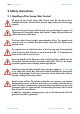
SMA Technologie AG Safety Instructions 3 Safety Instructions 3.1 Handling of the Sunny Mini Central All work on and in the Sunny Mini Central must be carried out by a qualified electrician. The electrician must be approved by the local energy supplier. Open and close the Sunny Mini Central only as described in section 10 "Opening and Closing the Sunny Mini Central" (Page 58) and follow the safety instructions listed there. The Sunny Mini Central weighs approximately 63 kg.
Safety Instructions SMA Technologie AG Follow the instructions in the pictograms, signs and labels on each inverter and ensure that they are legible at all times. General safety rules for working on photovoltaic systems: 1. Disconnecting the device Before you start to work on the unit, disconnect all wires which could carry voltage to the area you are working on! 2. Protect against reenergizing To prevent the device from being reenergized ensure that you block or lock it! 3.
SMA Technologie AG Safety Instructions 3.2 Installer's Responsibilities Each person working on an electrical device is responsible for the safety of all persons involved and for the safety of the device. Be sure to observe all standards and regulations applicable to the installation and site.
SMA Technologie AG Overview of the Device 4 Overview of the Device 4.1 Identification You can identify the Sunny Mini Central with the aid of the name plate (see figure below). The name plate is found on the right-hand side of the housing (when viewed from the front). It contains information regarding the device type, serial number, devicespecific key data, the CE mark and SMA contact information. The following is an example of a Sunny Mini Central SMC 6000A name plate: SMA Technologie AG www.SMA.
SMA Technologie AG Overview of the Device 4.
SMA Technologie AG Overview of the Device Wall bracket and rear panel 0,2 7,0 2,0 1,2 1,0 2,2 8,5 7,6 2,0 1,2 2,6 2,6 7,8 11,0 8,6 2,2 43,3 Holes for wall bracket Specifications in cm 48,7 Holes for optional single-use screws as anti-theft protection 0,9 (4 x) 1,2 1,2 5,8 Page 14 2,5 SMC50A_60A-IEN073320 2,5 5,8 Installation Guide
SMA Technologie AG Overview of the Device 4.3 Electronic Solar Switch (ESS) The Sunny Mini Central is equipped with the integrated electronic DC loaddisconnecting switch ESS. This reliably prevents the arcing that usually occurs when disconnecting the inverter from the PV generator, which can cause personal injury and may damage the inverter connections.
SMA Technologie AG Overview of the Device 4.
SMA Technologie AG Overview of the Device A Varistors (Page 65) B Connection terminals for communication (Page 48) C Socket for communication Piggy-Back (RS232, RS485, radio) (Page 48) D Jumper for communication (Page 48) E Sunny Display (Page 54) F Jumper for fan testing (Page 69) G Operating status LEDs (Page 55) H Connection terminals for mains cable (AC) (Page 41) I Cable duct for mains cable (AC) (Page 41) J Flat connection for grounding the cable shield for RS232 and RS485 communi
SMA Technologie AG Installation 5 Installation 5.1 Selecting an Installation Location No. Checkpoint Control Location The installation location and method of installation is suitable for the weight of approximately 63 kg and the dimensions of 468 mm x 613 mm x 242 mm (width x height x depth) of the Sunny Mini Central. 613 mm 1 468 mm 2 24 mm 63 kg 2 Page 18 The following minimum clearances to walls, other devices or objects must be observed to guarantee sufficient heat dissipation.
SMA Technologie AG Installation No. Checkpoint Control 3 If several Sunny Mini Central units are installed in areas where high ambient temperatures are to be expected, the individual Sunny Mini Central units must be far enough apart to ensure that the individual Sunny Mini Central units do not intake the cooling air of the neighboring unit. If necessary, increase the clearances and ensure that the device is sufficiently ventilated! 4 The Sunny Mini Central is accessible at any time (e.g.
SMA Technologie AG Installation No. Checkpoint Control Position 11 The Sunny Mini Central is mounted vertically on a wall, or if it is absolutely necessary, tilted back to an angle of max. 45°. 12 The Sunny Mini Central is installed so that it is not slanting forward. 13 The Sunny Mini Central is not installed horizontally. 14 The Sunny Mini Central should ideally be installed at eye level to allow operating conditions to be read at all times.
SMA Technologie AG Installation 5.
SMA Technologie AG Installation 5.3 Mounting the Sunny Mini Central Only use the provided wall bracket for installation! When mounting the device, be sure to take into account the weight of the Sunny Mini Central of 63 kg! Step Instruction Mounting the Wall Bracket 1 For mounting the wall bracket, use two to four of the six holes in the middle. 2 Mark the positions of the drill holes by using the wall bracket as a drilling template (see Page 14 for a sample).
SMA Technologie AG Step Installation Instruction Mounting the Sunny Mini Central 4 5 When transporting and installing the Sunny Mini Central, use the ergonomic handles at the top and bottom at the sides of the Sunny Mini Central (A), or the housing opening, for example by inserting a steel bar (B) (diameter max. 30 mm). A B Hang the Sunny Mini Central using the mounting holes on the rear face into the wall bracket.
SMA Technologie AG Installation Step Instruction 8 Close the recessed grips with the handle covers provided in the accessories kit. They are required to adequately prevent insects entering the unit! 2 1 If required, new handle covers can be ordered from SMA (contact: see Page 92). Optional Anti-theft Protection 9 To protect the Sunny Mini Central against theft, the rear face can be secured to the wall at the bottom using 2 so-called single-use bolts.
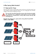
SMA Technologie AG Electrical Connection 6 Electrical Connection 6.
SMA Technologie AG Electrical Connection 6.2 Connection Procedure When connecting the unit to the power supply, do not deviate from the sequence described here! The following figure shows the assignment of the individual housing ducts on the base of the Sunny Mini Central.
SMA Technologie AG Electrical Connection 6.3 Connection of the DC Input 6.3.1 Requirements For connecting the DC input, the following requirements must be satisfied: 1. The connected strings must consist of modules of the same type and number and should have an identical orientation and tilt. 2. The connecting wires of the solar modules must be equipped with plug connectors to allow the eight DC plug connectors of the Sunny Mini Central to be connected to it.
SMA Technologie AG Electrical Connection 6.3.2 Connection of PV Strings NOTICE! The AC side of the Sunny Mini Central must be disconnected from the grid before you connect the PV strings to the Sunny Mini Central! To connect up the PV strings, follow these steps: Step Instruction 1 Remove the Electronic Solar Switch on the underside of the Sunny Mini Central.
SMA Technologie AG Step Electrical Connection Instruction 6 Connect up the faultless PV generator strings as indicated on the right. 7 Close the unused DC input sockets with the caps included in the delivery. 8 Reinsert the handle of the Electronic Solar Switch in the socket on the underside of the Sunny Mini Central. The Electronic Solar Switch can be damaged if it has not been attached properly.
Electrical Connection SMA Technologie AG 6.3.3 Reverse Current Advice on Generator Configuration for PV Systems Using the Sunny Mini Central In contrast to the Sunny Boy string inverters, three and more strings are usually connected in parallel in the PV generator of a system using the Sunny Mini Central. This does not sound particularly spectacular but it has practical consequences because, in such large generators, certain faults which are totally uncritical in string systems must be allowed for.
SMA Technologie AG Electrical Connection Despite the fact that these faults are very unlikely, and extremely rare in practice, preventative measures must still be taken. After all, these types of faults carry a high potential for damage and danger, since all modules in the affected string may be damaged and the local heating may also cause secondary damage.
Electrical Connection SMA Technologie AG How Can Reverse Current in the Modules be Prevented? First we must explain that bypass diodes which are the current state-of-the-art in module construction do not influence the reverse current in the module, but only reduce the effect of any shadowing which may occur. In order to prevent or to limit the reverse current into the modules, the following standard methods can be applied: 1.
SMA Technologie AG Electrical Connection Design Notes Check the following points below: Step Test 1 Do all the strings have the same number of series-connected modules? 2 How high is the maximum reverse current in a defective string at nominal conditions? Example: generator with 4 strings of modules at 5 A short-circuit current The maximum reverse current is 3 x 5 A = 15 A.
SMA Technologie AG Electrical Connection 6.4 Connecting the AC Output 6.4.1 Requirements For connecting the AC output, the following requirements must be satisfied: 1. Connection Requirements When connecting an inverter to the public grid, follow the connection requirements of the local grid operator! The Sunny Mini Central is designed for operation on 220 V - 240 V grids.
SMA Technologie AG 2. Electrical Connection Grid Impedance Due to a high grid impedance, a high line resistance or a high voltage at the feedin point, a high AC voltage may result at the connection point of the Sunny Mini Central. In Germany, the 10-minute average of the output voltage (Uac) of the Sunny Mini Central is limited to 253 V according to DIN VDE 0126-1-1.
SMA Technologie AG Electrical Connection The diagram shows the respective curves for a grid voltage without mains supply. A maximum possible feed-in power per phase (X axis) is obtained for the respective curves depending on the grid impedance (Y axis). With three-phase connection and symmetrical feeding, the maximum possible feed-in power per phase is approximately doubled. Example: The grid voltage without mains supply is 230 V - The grid impedance at the terminal is 1.
SMA Technologie AG 3. Electrical Connection Cable Connection The connection terminals in the Sunny Mini Central are suitable for wire cross-sections of up to 25 mm². External diameter Wire crosssection The external diameter of the cable must therefore be between 11 mm and 25 mm. If you use a cable with a cross-section smaller than 14 mm (11 mm minimum), the rubber bushing in the screw fitting must be replaced by the one included with the inverter at delivery.
SMA Technologie AG Electrical Connection Output losses of the Sunny Mini Central SMC 5000A Output losses Do not use cables where losses will exceed 1.0 % Cable length The following maximum cable lengths are possible for the different cable crosssections: Cable cross-section 4.0 mm² 6.0 mm² 10.0 mm² 16.0 mm² 25.0 mm² Max. cable length 12.4 m 18.6 m 31.1 m 49.7 m 77.
SMA Technologie AG Electrical Connection Output losses of the Sunny Mini Central SMC 6000A Output losses Do not use cables where losses will exceed 1.0 % Cable length The following maximum cable lengths are possible for the different cable crosssections: Cable cross-section 4.0 mm² 6.0 mm² 10.0 mm² 16.0 mm² 25.0 mm² Max. cable length 10.3 m 15.5 m 25.9 m 41.4 m 64.
Electrical Connection 6. SMA Technologie AG Line Circuit Breaker The selection of the correct line circuit breaker depends on various factors. For detailed information for the rating of a line circuit breaker, please refer to section 6.4.3 "The Line Circuit Breaker" (Page 44). No loads should be connected to this power circuit! A circuit breaker's load disconnecting properties can be utilized to disconnect the inverter from the grid under load. A screw fuse element, e.g.
SMA Technologie AG Electrical Connection 6.4.2 Connecting the AC Output To connect up the AC output, follow these steps: Step 1 Instruction Check the grid voltage! For Germany, the following applies: If the grid voltage is constantly higher than 253 V, the Sunny Mini Central will not be fully operational. In this case, contact the local grid operator for assistance. The inverter can temporarily feed power into the grid with a maximum output voltage of 260 V.
SMA Technologie AG Electrical Connection Step 5 Instruction Connect the protective earth (PE) of the mains cable to the right terminal of the terminal block (see figure to the right). To do this, the PE wire must be 5 mm longer than the L and N wires! PE PE conductor connection If a second protective earth connection is required, you can use the additional connection terminal directly on the Sunny Mini Central's housing for this purpose. Proceed as follows: 1.
SMA Technologie AG Step 7 Electrical Connection Instruction Secure the housing cover by evenly tightening the two middle screws first. Then tighten the four remaining screws as well and do not forget to also reattach the washers. The toothing of the washers must face toward the housing cover. The screws must be tightened with approximately 6 Nm torque in order to guarantee both the sealing of the housing and the grounding of the cover.
Electrical Connection SMA Technologie AG 6.4.3 The Line Circuit Breaker Factors that Determine the Selection Various factors should be taken into account when selecting line circuit breakers.
SMA Technologie AG Electrical Connection Rating of the Circuit Breakers Example for the thermal rating for a line circuit breaker in a photovoltaic powergenerating system operated in parallel with the low voltage grid. We assume a PV system with 9 Sunny Mini Central inverters with three inverters per phase.
Electrical Connection SMA Technologie AG Example for the thermal selection of a 32 A line circuit breaker with B sensitivity with no gap between the circuit breakers: When selecting line circuit breakers, a number of load factors need to be taken into account. These can be found in the respective manufacturer's data sheets. For example, one manufacturer's circuit breaker may be designed for an ambient temperature of 50 °C.
SMA Technologie AG Electrical Connection As well as the thermal rating of the circuit breakers, the applicable DIN VDE standards must also be taken into account. The main ones that apply here are: • DIN VDE 0100, part 410 • DIN VDE 0100, part 430 • DIN VDE 0298, part 4 In special applications the relevant standards must be followed.
The Communication Interface SMA Technologie AG 7 The Communication Interface Installation or replacement of the communication interface is only to be carried out by a qualified electrician. The communication interface is used to communicate with SMA communication devices (e.g. Sunny Boy Control, Sunny WebBox) or a PC with appropriate software (e.g. Sunny Data Control). Depending on the selected communication interface, up to 2500 inverters can be interconnected.
SMA Technologie AG The Communication Interface 7.1 Connecting RS232, RS485, Sunny Beam Electrostatic discharges are an acute danger to the Sunny Mini Central and to the communications interface. Ground yourself by touching PE or a non-coated part of the housing before removing the communication interface from the packaging, and before touching any components within the Sunny Mini Central. Read the communication device manual before beginning installation work. Further wiring details can be found there.
SMA Technologie AG The Communication Interface F E D C B A A Housing feed-throughs in the base of the Sunny Mini Central B Cable route (gray surface) C PE connector D Screw terminals for connection of the communication wires E Jumper slots F Interface port 7.1.1 Jumper Functions Jumper A Jumper B Jumper C RS232 - - - RS485 termination bias 1 bias 2 Sunny Beam - - - A detailed description of the jumper functions can be found in the communication device manual.
SMA Technologie AG Commissioning the Sunny Mini Central 8 Commissioning the Sunny Mini Central Proceed with commissioning the Sunny Mini Central only after: • the housing cover is securely screwed shut, • the DC cables (PV strings) are fully connected and the unused DC plug connectors on the bottom of the housing are closed using the protective caps, • the Electronic Solar Switch is securely attached, • the AC (power) cable is fully connected and • the line circuit breaker is laid out correctly.
SMA Technologie AG Commissioning the Sunny Mini Central 8.1 Display After a normal grid connection of the Sunny Mini Central, it takes approximately one minute until the following display messages are shown alternately. For this, the DC and AC connections must be wired correctly and the circuit breaker must be switched on.
SMA Technologie AG Commissioning the Sunny Mini Central Display Description In case of failures E-today 0 Wh Mode Disturbance Disturbance Vac-Bfr at: present: 261V 245 V In case of a failure, the message "Disturbance" will be indicated in the status bar. The exact error message follows. For example, if the "Disturbance" message shown here is displayed immediately after connection, it may be due to the fact that the AC wire is not correctly connected or the circuit breaker is not switched on.
SMA Technologie AG Commissioning the Sunny Mini Central 8.1.1 Setting the Language of the Sunny Display You can set the language of the Sunny Display using the switches on the underside of the display assemblies inside the Sunny Mini Central. Proceed as follows: 1. Open the Sunny Mini Central as described in section 10.2 "Opening of the Sunny Mini Central" (Page 59). 2. Set the switches for the required language, as shown below.
SMA Technologie AG Commissioning the Sunny Mini Central 8.2 LEDs After a normal grid connection of the Sunny Mini Central, it takes approximately one minute until the following blink code is displayed. For this, the DC and AC inputs must be correctly connected and the circuit breaker must be activated. The blink codes shown before that only have the purpose of indicating the initialization of the Sunny Mini Central and the process of controlling whether the power supply requirements are fulfilled.
SMA Technologie AG Commissioning the Sunny Mini Central Working Mode Green LED is on. The Sunny Mini Central is in normal working mode. The green LED is continuously on. In Case of Failures In case the Sunny Mini Central detects an error, this is indicated through a blink code of the yellow and red LEDs. For example, if the yellow LED glows for 5 seconds immediately after connection, then goes out for 3 seconds and then flashes briefly twice, there is a grid fault.
SMA Technologie AG Hand-over to the Operator 9 Hand-over to the Operator After installing the Sunny Mini Central successfully, hand the system over to the operator. To do so, please use the following check list. No. Checkpoint Control What the operator should know: 1 operating principles of the PV system 2 switching the PV system on and off 3 meaning of the LEDs and display messages 4 maintenance and cleaning (handle covers, LEDs, display,...
Opening and Closing the Sunny Mini Central SMA Technologie AG 10 Opening and Closing the Sunny Mini Central 10.1 Safety Instructions Follow all safety instructions described in section 3 "Safety Instructions" (Page 9). High voltages are present in the device! Inappropriate opening or closing of the Sunny Mini Central can cause serious material damage or injury to persons which could be fatal.
SMA Technologie AG Opening and Closing the Sunny Mini Central 10.2 Opening of the Sunny Mini Central Follow the sequence described below and all safety instructions in section 10.1 "Safety Instructions" (Page 58)! Step Instruction 1 Switch the line circuit breaker to its "off" position, make sure it cannot be switched back on, and test to make sure no voltage is present. Off! 2 Pull the handle of the Electronic Solar Switch off the Sunny Mini Central. 1. 2. 3.
Opening and Closing the Sunny Mini Central SMA Technologie AG 10.3 Closing of the Sunny Mini Central Follow the sequence described below and all safety instructions in section 10.1 "Safety Instructions" (Page 58)! Step 1 Instruction Secure the housing cover by evenly tightening the two middle screws with the corresponding washers first. The toothing of the washers must face toward the housing cover.
SMA Technologie AG Step 4 Opening and Closing the Sunny Mini Central Instruction Reinsert the handle of the Electronic Solar Switch in the socket on the underside of the Sunny Mini Central. The Electronic Solar Switch can be damaged if it has not been attached properly. The handle must be firmly attached to the Electronic Solar Switch's socket, and rest against the housing. Check that the handle is positioned correctly before recommissioning the inverter.
SMA Technologie AG Troubleshooting / Problem Solving 11 Troubleshooting / Problem Solving The Sunny Mini Central is a complex high-technology device. As a result, the possibilities for fixing faults on site are limited to just a few items.
SMA Technologie AG Troubleshooting / Problem Solving 11.2 The red LED is Continuously on 11.2.1 Ground Fault Testing If the red LED on the Sunny Mini Central is continuously illuminated, it should be checked whether there is a ground fault in the PV generator. Follow the safety instructions in section 10.1 "Safety Instructions" (Page 58) and proceed as follows: Step Instruction 1 Disconnect the Sunny Mini Central from both the DC and AC connections, as described in section 10.
SMA Technologie AG Troubleshooting / Problem Solving Step 3 Instruction Repeat points 3 and 4 for each string. Event Measure You have found a ground Restart the Sunny Mini Central as described fault. from step 7 onwards, but without reconnecting the faulty string. The PV generator's installation engineer has to fix the ground fault before you can reconnect this string. You have found no ground It is likely that one of the thermally monitored fault. varistors is defective.
SMA Technologie AG Troubleshooting / Problem Solving 11.2.2 Checking the Varistors Varistors are wearing parts. Their functioning diminishes with age or following repeated responses as a result of overvoltages. It is therefore possible that one of the thermally monitored varistors has lost its protective function. You can now check these varistors in the following way, paying attention to the safety instructions in section 10.
SMA Technologie AG Troubleshooting / Problem Solving Step 3 Instruction Replace the varistor concerned with a new one as shown in the illustration to the right. Ensure the varistor is installed the right way round! If you do not receive a special tool for operating the terminal clamps together with your replacement varistors, please contact SMA. As an alternative, the terminal contacts can be operated using a suitable screwdriver.
SMA Technologie AG Maintenance and Cleaning 12 Maintenance and Cleaning The Sunny Mini Central has been constructed so that maintenance is kept to a minimum. To guarantee safe operation, it is usually adequate to observe the following principles: • Check the Sunny Mini Central visually for damage approximately every two months. • If necessary, clean the LEDs and the display with a damp cloth. Solvents, abrasives or corrosive liquids must not be used.
Maintenance and Cleaning Step SMA Technologie AG Instruction 1 Disconnect the Sunny Mini Central from both the DC and AC connections, paying attention to the safety instructions in section 3 "Safety Instructions" (Page 9). 2 Wait for the fans to stop rotating. 3 Push the two latches at the upper edge of the black plastic cover to one side and remove it carefully with the fan guards mounted behind. Clean the fan guards with a soft brush, a paint brush, a cloth or compressed air.
SMA Technologie AG Maintenance and Cleaning 12.1.2 Checking the Fans If necessary, there are two different ways to check the fans are functional: • Set the "Fan Test" parameter to "1" in the installer mode (using Sunny Data, Sunny Data Control, the Sunny Boy Control data logger or Sunny WebBox), or • place the jumper on the controller board (the jumper required to check the fans is included in the Sunny Mini Central accessories kit).
SMA Technologie AG Maintenance and Cleaning Step Instruction Setting the Jumper 1 Open the Sunny Mini Central as described in section 10.2 "Opening of the Sunny Mini Central" (Page 59). 2 Place the jumper on the controller board socket, as laid out below. Jumper position for checking the fans 3 Close the Sunny Mini Central as described in section 10.3 "Closing of the Sunny Mini Central" (Page 60). 4 The Sunny Mini Central recognizes the jumper only after the system has been restarted (i.e.
SMA Technologie AG Maintenance and Cleaning 12.1.3 Cleaning the Handle Covers There are handle covers on either side of the Sunny Mini Central. The Sunny Mini Central sucks air in from underneath via the fan and blows it out again on the upper sides. For optimum heat dissipation within the device, you have to clean both handle covers. Proceed as follows when cleaning the handle covers: Step Instruction 1 The handle covers of the Sunny Mini Central are to be found on the sides of the housing.
SMA Technologie AG Maintenance and Cleaning 12.2 Inspection of the Electronic Solar Switch Check the Electronic Solar Switch for wear before you attach it. To do this, check the metal tongues on the inside of the plug for brown discoloration. Metal tongues If one of the metal tongues is completely burned out (see figure below), then the Electronic Solar Switch can no longer safely disconnect the DC side. Replacements for damaged Electronic Solar Switch handles are available from SMA.
SMA Technologie AG Decommissioning 13 Decommissioning 13.1 Disassembly You must follow the sequence described below and all safety instructions in sections 3 and 10.1! Step Instruction 1 Open the Sunny Mini Central as described in section 10.2 "Opening of the Sunny Mini Central" (Page 59). 2 Disconnect the AC cable. 3 Close the Sunny Mini Central with the six screws and the corresponding washers.
SMA Technologie AG Decommissioning Step 8 Instruction When transporting the Sunny Mini Central, use the ergonomic handles at the top and bottom at the sides of the Sunny Mini Central (A) or the housing opening, for example, by sliding a steel bar through it (B) (diameter max. 30 mm). A B 13.2 Packaging If possible, please pack the Sunny Mini Central in the original packaging.
SMA Technologie AG Technical Data 14 Technical Data 14.1 Sunny Mini Central SMC 5000A Description Short descr. Setting UPV 0 600 V (based on -10 °C cell temperature) PV Generator Connection Data Max. input open circuit voltage Input voltage, MPP range Max. input current Max.
SMA Technologie AG Technical Data Description Short descr. Setting Grid Connection Data Nominal output power PACnom 5000 W Peak output power PAC, max 5500 W Nominal output current IACnom Max. output current IAC, max 26 A Harmonic distortion of output current (at KUgrid < 2 %, PAC > 0.5 PACnom) KIAC Short-circuit proofing 21.7 A <4% current control Nominal operational voltage UACnom 230 V Operating range, grid voltage (complying with DIN VDE 0126-1-1) UAC 198 ...
SMA Technologie AG Description Technical Data Short descr. Setting Max. efficiency ηmax 96,1 % CEC rebate efficiency euro 95,2 % Efficiency Weight Weight a) approx. 62 kg The Sunny Mini Central can temporarily feed power into the grid with a maximum output voltage of 260 V. However, DIN VDE 0126-1-1 stipulates that the average voltage over 10 minutes must not exceed 253 V. That means for example, if the grid voltage is constantly 254 V, the inverter disconnects itself from the grid.
SMA Technologie AG Technical Data 14.2 Sunny Mini Central SMC 6000A Description Short descr. Setting Max. input open circuit voltage UPV 0 600 V (based on -10 °C cell temperature) Input voltage, MPP range UPV 213 V - 600 V @ UACmin (246 V - 600 V DC @ 230 V AC) Max. input current IPV, max 26 A Max.
SMA Technologie AG Technical Data Description Short descr. Setting Nominal output power PACnom 6000 W Peak output power PAC, max 6000 W Nominal output current IACnom 26 A Max. output current IAC, max 26 A Grid Connection Data Harmonic distortion of output current KIAC (at KUgrid < 2 %, PAC > 0.5 PACnom) <4% Short-circuit proofing current control Nominal operational voltage UACnom 230 V Operating range, grid voltage (complying with DIN VDE 0126-1-1) UAC 198 ...
SMA Technologie AG Technical Data Description Short descr. Setting Max. efficiency max 96.1 % CEC rebate efficiency euro 95,2 % Efficiency Weight Weight a) approx. 63 kg The Sunny Mini Central can temporarily feed power into the grid with a maximum output voltage of 260 V. However, DIN VDE 0126-1-1 stipulates that the average voltage over 10 minutes must not exceed 253 V. That means for example, if the grid voltage is constantly 254 V, the inverter disconnects itself from the grid.
SMA Technologie AG Technical Data 14.3 General Data General Data Protection rating in accordance IP65 with DIN EN 60529 Climatic conditions (DIN EN 50178:1998-04): Location of type C: class 4K4H Extended temperature range: -25 °C to +60 °C Extended humidity range: 0 - 100 % Extended air pressure range: 79.5 kPa to 106 kPa Transport of type E: class 2K3 Temperature range: -25 °C to +70 °C Max.
SMA Technologie AG Technical Data 14.4 Sunny Mini Central Operating Parameters Unauthorized changes to the operating parameters may result in: • injury or accidents as a result of changing the internal safety specifications of the Sunny Mini Central, • voiding the Sunny Mini Central operating approval certificate, • voiding the Sunny Mini Central warranty.
SMA Technologie AG Technical Data Name Explanation Control Current regulation switching. If the operating parameter "Control" is set to "Auto", the inverter automatically chooses the optimal type of current regulation. If the operating parameter "Control" is set to "Grid", the inverter regulates on the grid side. If set to "Bridge", the inverter regulates on the bridge side. This setting can be a corrective measure in the event of difficult grid characteristics.
SMA Technologie AG Technical Data Name Explanation Fac-Pderating Frequency-dependent output limitation. Fac-Start delta For setting the frequency-dependent output derating in the operating mode "Off Grid". Further information on this topic can be found in the Sunny Island operating manual. Fac-Tavg Averaging time of grid frequency measurement. Fan-Test By setting the "Fan-Test" parameter to "1" you can check functionality of the fan.
SMA Technologie AG Technical Data Name Explanation Ripple-Ctl-Frq The Ripple-Ctl-Frq, Ripple-Ctl-Lev, Ripple-Ctl-Rcvr parameters are intended to handle ripple control signals from the Sunny Mini Centrals. These parameters are not available for all Sunny Mini Centrals. These parameters may only be changed after prior agreement with SMA Technologie AG. Ripple-Ctl-Lev Ripple-Ctl-Rcvr SMA-SN Serial number of the Sunny Mini Central. Software-BFR Firmware version of the operation control unit (BFR).
SMA Technologie AG Technical Data Name Explanation Usoll-Konst PV desired voltage for constant operational voltage. These parameters are only important when the "Betriebsart" parameter is set to U-konst.
SMA Technologie AG Technical Data 14.4.2 Parameter Settings for Germany Grayed out parameters are only displayed in installer mode. The table below contains the parameters that are applicable in Germany. Name Short Value range descr. Default setting SMC 5000A SMC 6000A 253 253 0 0 ACVtgRPro V 230 ... 300 AntiIslandAmpl * grd 0 ... 10 AntiIslandFreq * mHz 0.1 ...
SMA Technologie AG Technical Data Name Short Value range descr. Default setting SMC 5000A SMC 6000A 0 0 LDVtgC V 0 ... 50 Pmax W 0 ... 6050 5500 6000 P-Wind-Mid W 0 ... 6000 2000 2000 P-Wind-Ramp W/s 10 ... 2000 1000 1000 Ripple-Ctl-Frq Hz 105 ... 1605 1605 1605 Ripple-Ctl-Lev % 0.5 ... 8 8 8 disable disable 1000 1000 no function no function permanent permanent Ripple-Ctl-Rcvr Riso-min disable, enable, auto kOhm 0 ... 10000 Speicherfkt.
SMA Technologie AG Technical Data Parameters designated with * are safety-related grid monitoring parameters. To change the SMA grid guard parameters, you must enter your personal SMA grid guard password (Inst.-Code). Call the SMA Serviceline to obtain your personal SMA grid guard password. 14.4.3 Country-specific Parameter Settings You can see the default settings of the Sunny Mini Central on the name plate (see section 4.1 "Identification" (Page 12)).
SMA Technologie AG Technical Data Sunny Mini Central SMC 6000A The parameters listed below represent country-specific settings and are only displayed in installer mode. All other parameters are international and can be viewed in the table in section 14.4.2. Name Short descr. Country settings Germany Australia Great Britain Italy Spain 253 253 253 253 253 GER/ VDE0126-1-1 AUS/ AS4777 GB/ G83 IT/ DK5950 SP/ RD1663 4 0.25 0.2 0.
SMA Technologie AG Technical Data 14.4.4 Fixed Parameters Grayed out parameters are only displayed in installer mode. The following parameters are displayed in the parameter list but cannot be changed: Name Short descr.
SMA Technologie AG Contact 15 Contact If you have any questions or technical problems concerning the Sunny Mini Central, contact our hotline. Please have the following information available when you contact SMA: • Inverter type • Serial number of the Sunny Mini Central. • Type and number of modules connected • Communication method • Blink code or display of the Sunny Mini Central Address: SMA Technologie AG Hannoversche Strasse 1 - 5 34266 Niestetal Germany Tel.
SMA Technologie AG Installation Guide Contact SMC50A_60A-IEN073320 Page 93
Legal Restrictions SMA Technologie AG The information contained in this document is the property of SMA Technologie AG. Publishing its content, either partially or in full, requires the written permision of SMA Technologie AG. Any internal company copying of the document for the purposes of evaluating the product or its correct implementation is allowed and does not require permission. Exclusion of liability The general terms and conditions of delivery of SMA Technologie AG shall apply.
Sales Solar Technology www.SMA.de SMA Technologie AG Hannoversche Strasse 1–5 34266 Niestetal, Germany Tel. : +49 561 9522 4000 Fax: +49 561 9522 4040 E-mail: sales@SMA.