
Datasheet


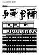

Pressure Characteristics (Representative values)
Conditions: Inlet pressure 0.7 MPa, Outlet pressure 0.2 MPa, Flow rate 20 l/min (ANR)
0.6
0.
5
0.
4
0.
3
0.
2
0.
1
0
0 25 50 75 100 125 150
AC10
M5 x 0.8
Outlet pressure (MPa)
0
0
0.6
0.
5
0.
4
0.
3
0.
2
0.
1
0
200 400 600 800
AC20
Rc1/4
Outlet pressure (MPa)
0.5
0.6
0.
4
0.
3
0.
2
0.
1
0
500 1000 1500
AC25
Rc3/8
Outlet pressure (MPa)
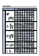
Flow Characteristics (Representative values) Condition: Inlet pressure 0.7 MPa
Flow rate (
l
/min (ANR)) Flow rate (
l
/min (ANR)) Flow rate (
l
/min (ANR))
0.25
0.
2
0
0.15
0 0.2 0.3 0.4 0.5 0.6 0.7 0.8 0.9 1.0
Inlet pressure (MPa)
Outlet pressure (MPa)
AC20
0.25
0.3
0.2
0.15
0
0 0.2 0.3 0.4 0.5 0.6 0.7 0.8 0.9 1.0
Inlet pressure (MPa)
Outlet pressure (MPa)
AC10
0.25
0.2
0
0.15
0 0.2 0.3 0.4 0.5 0.6 0.7 0.8 0.9 1.0
Inlet pressure (MPa)
Outlet pressure (MPa)
AC40-06
0.25
0.
2
0
0.15
0 0.2 0.3 0.4 0.5 0.6 0.7 0.8 0.9 1.0
Inlet pressure (MPa)
Outlet pressure (MPa)
AC25
0.25
0.
2
0
0.15
0 0.2 0.3 0.4 0.5 0.6 0.7 0.8 0.9 1.0
Inlet pressure (MPa)
Outlet pressure (MPa)
AC30
0.25
0.
2
0
0.15
0 0.2 0.3 0.4 0.5 0.6 0.7 0.8 0.9 1.0
Inlet pressure (MPa)
Outlet pressure (MPa)
AC40
0
0.6
0.5
0.4
0.3
0.2
0.1
0
1000 2000 3000
AC40
Rc1/2
Flow rate
(
l
/min (ANR))
Outlet pressure (MPa)
0
0.6
0.
5
0.
4
0.
3
0.
2
0.
1
0
500 1000 1500
AC30
Rc3/8
Flow rate (
l
/min (ANR))
Outlet pressure (MPa)
0
0.6
0.5
0.4
0.3
0.2
0.1
0
AC60
Rc1
Flow rate
(
l
/min (ANR))
Outlet pressure (MPa)
4000 6000 80002000 10000
0
0.6
0.5
0.4
0.3
0.2
0.1
0
AC55
Rc1
Flow rate
(
l
/min (ANR))
Outlet pressure (MPa)
4000 6000 80002000 10000
0
0.6
0.
5
0.
4
0.3
0.
2
0.
1
0
AC50
Rc1
Flow rate (l/min (ANR))
Outlet pressure (MPa)
4000 6000 80002000 10000
0.6
0.5
0.4
0.3
0.2
0.1
0
0 1000 2000 3000 4000 5000
AC40-06
Rc3/4
Flow rate
(
l
/min (ANR))
Outlet pressure (MPa)
Set
point
Set
point
Set
point
Set
point
Set
point
Set
point
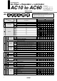
Series AC10 to AC60
Pressure Characteristics (Representative values) Conditions: Inlet pressure 0.7 MPa, Outlet pressure 0.2 MPa, Flow rate 20 l/min (ANR)
Mounting and Adjustment
1. A knob cover is available to prevent careless operation of the
knob. Refer to page 90 for details.
Caution
Selection
1. Float type auto drain
Operate under the following conditions to avoid malfunction.
<N.O. type>
• Operating compressor: 0.75 kW (100
l/min (ANR)) or more.
When using 2 or more auto drains, multiply the value above
by the number of auto drains to find the capacity of the
compressors you will need.
For example, when using 2 auto drains, 1.5 kW (200 l/min
(ANR)) of the compressor capacity is required.
• Operating pressure: 0.1 MPa or more.
<N.C. type>
• Operating pressure for AD17/27: 0.1 MPa or more.
• Operating pressure for AD37/47: 0.15 MPa or more.
2. Use a regulator or filter regulator with backflow function when
mounting a 3-port valve for residual pressure release on the IN
side to ensure the release of the residual pressure. Otherwise,
residual pressure will not be fully released.
Warning
Piping
1. When mounting a check valve, make sure the arrow (IN side)
points in the correct direction of air flow.
Warning
Air Supply
1. Use an air filter with 5 µm or less filtration rating on the inlet
side of the valve to avoid any damage to the seat caused by
dust when mounting a 3-port valve for residual pressure
release on the inlet side.
Caution
0.25
0.
2
0
0.15
0 0.2 0.3 0.4 0.5 0.6 0.7 0.8 0.9 1.0
Inlet pressure (MPa)
Outlet pressure (MPa)
AC50
0.25
0.
2
0
0.15
0 0.2 0.3 0.4 0.5 0.6 0.7 0.8 0.9 1.0
Inlet pressure (MPa)
Outlet pressure (MPa)
AC55
0.25
0.
2
0
0.15
0 0.2 0.3 0.4 0.5 0.6 0.7 0.8 0.9 1.0
Inlet pressure (MPa)
Outlet pressure (MPa)
AC60
Set
point
Set
point
Set
point
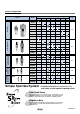
Specific Product Precautions
1. When releasing air at the intermediate position using a T-
interface on the inlet side of the lubricator, lubricant may back
flow. Therefore, releasing air that does not contain traces of
lubricant is not possible.
To release air that does not contain traces of lubricant, use a
check valve (AKM series) on the inlet side of the lubricator to
prevent a backflow of the lubricant.
2. If a residual pressure-release 3-port valve
is mounted on the
inlet side of the lubricator, causing a backflow of air, it can
result in a backflow of oil or damage to internal parts. Please
do not use it in this fashion.
3. An F.R.L. unit shipped from the plant has its model number
labeled. However, components that are combined together
during the distribution process do not have a label on them.
Caution
Air Combination
Series AC10 to AC60
4