
Datasheet


8
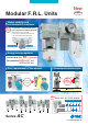
Air Combination
Series AC10-A to AC40-A
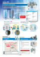
AC
AF
AR
ALAW
ALAF
ARAF
AFM
ARAW
AFM
AF Attachment
AFM / AFD
ARALAW
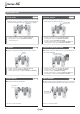
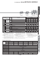
Symbol
Description
q
Body size
10 20 25 30 40
y
Semi-standard
i
Air filter
drain port
Note 13)
—
With drain cock
J
Note 14)
Drain guide 1/8
—
———
Drain guide 1/4
——
W
Note 15)
Drain cock with barb fitting (for ø6 x ø4 nylon tube)
——
+
j
Lubricator lubricant
exhaust port
—
Without drain cock
3
Note 16)
Lubricator with drain cock
+
k
Exhaust
mechanism
—
Relieving type
N
Non-relieving type
+
l Flow direction
—
Flow direction: Left to right
R
Flow direction: Right to left
+
m Pressure unit
—
Name plate and pressure gauge in imperial units: MPa
Z
Note 17)
Name plate, caution plate for bowl, and pressure gauge in imperial units: psi, °F
Note 18)
Note 18)
Note 18)
Note 18)
Note 18)
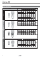
Model
AC10-A AC20-A AC25-A AC30-A AC40-A AC40-06-A
Component
Air Filter [AF]
AF10-A AF20-A AF30-A AF30-A AF40-A AF40-06-A
Regulator [AR]
AR10-A AR20-A AR25-A AR30-A AR40-A AR40-06-A
Lubricator [AL]
AL10-A AL20-A AL30-A AL30-A AL40-A AL40-06-A
Port size M5 x 0.8 1/8, 1/4 1/4, 3/8 1/4, 3/8 1/4, 3/8, 1/2 3/4
Pressure gauge port size [AR]
1/16 1/8
Fluid Air
Ambient and fluid temperature
–
5 to 60 °C (with no freezing)
Proof pressure 1.5 MPa
Max. operating pressure
1.0 MPa
Set pressure range [AR]
0.05 to 0.7 MPa
Nominal fi ltration rating [AF]
5 μm
Recommended lubricant [AL]
Class 1 turbine oil (ISO VG32)
Bowl material [AF/AL]
Polycarbonate
Bowl guard [AF/AL] —
Semi-standard (Steel)
Standard (Polycarbonate)
Construction [AR] Relieving type
Weight [kg] 0.27 0.40 0.68 0.83 1.53 1.66
Standard Specifi cations
AC40-AAC20-A
Note 1) Drain guide is NPT1/8 (applicable to the AC20-A) and NPT1/4
(applicable to the AC25-A to AC40-A). The auto drain port comes
with ø3/8" One-touch fi tting (applicable to the AC25-A to AC40-A).
Note 2) Drain guide is G1/8 (applicable to the AC20-A) and G1/4 (applicable
to the AC25-A to AC40-A).
Note 3) Option G, M are not assembled and supplied loose at the time of
shipment.
Note 4) When pressure is not applied, condensate which does not start the
auto drain mechanism will be left in the bowl. Releasing the residual
condensate before ending operations for the day is recommended.
Note 5) If the compressor is small (0.75 kW, discharge fl ow is less than 100
L/min[ANR]), air leakage from the drain cock may occur during start
of operations. N.C. type is recommended.
Note 6) When the pressure gauge is attached, a 1.0 MPa pressure gauge
will be fi tted for standard (0.7 MPa) type. 0.4 MPa pressure gauge
for 0.2 MPa type (1.0 MPa pressure gauge only for the AC10-A).
Note 7) Not available with piping port size: 06
Note 8) The bracket position varies depending on the T-spacer or pressure
switch mounting.
Note 9) Pressure can be set higher than the specifi cation pressure in some
cases, but use pressure within the specifi cation range.
Note 10) Refer to Chemical data on page 38 for chemical resistance of the
bowl.
Note 11) A bowl guard is provided as standard equipment (polycarbonate).
Note 12) A bowl guard is provided as standard equipment (nylon).
Note 13) Float type auto drain: The combination of C and D is not possible.
Note 14) Without a valve function
Note 15) The combination of metal bowl: 2 and 8 is not available.
Note 16) When choosing with W: Filter drain port, the drain cock of a
lubricator will be with barb fi ttings.
Note 17) For pipe thread type: M5, NPT. MPa and psi are shown together
on the pressure unit. Cannot be used with M: Round pressure
gauge (with colour zone). Available by request for special.
Note 18)
: For pipe thread type: M5, NPT only
AC10-A