
Datasheet


Air Combination
Air Filter + Mist Separator + Regulator
AC20C to AC40C
AC C
30
03
DE
+
+
+
+
+
+
+
+
+
Description
Rc
NPT
G
Symbol
—
N
Note 1)
F
Note 2)
—
E
G
M
E1
E2
E3
E4
—
C
D
01
02
03
04
06
Thread type
Port size
Pressure
gauge
—
S
Note 4)
T
Note 4)
Pressure
switch
T-interface
Digital
pressure
switch
Float type
auto drain
1/8
1/4
3/8
1/2
3/4
Without auto drain
Float type auto drain (N.C.)
Float type auto drain (N.O.)
Without pressure gauge
Square embedded type pressure gauge (with limit indicator)
Round type pressure gauge (with limit indicator)
Round type pressure gauge (with colour zone)
Output: NPN output / Electrical entry: Wiring bottom entry
Output: NPN output / Electrical entry: Wiring top entry
Output: PNP output / Electrical entry: Wiring bottom entry
Output: PNP output / Electrical entry: Wiring top entry
b
a
c
—
V
V1
Note 5)
3-port valve for
residual pressure
release
d
25
30
40
20
Body size
Without attachment
Mounting position: AF+AFM+
S+AR
Mounting position: AF+AFM+
T+AR
Without attachment
Mounting position: AF+AFM+AR+
V
Mounting position: V+AF+AFM+ARK
JIS Symbol
Air Filter Mist Separator Regulator
—
2
6
8
C
6C
Filter
Mist separator
drain port
Note 7)
Bowl
—
1
Note 6)
—
N
Set pressure
Exhaust
mechanism
—
J
Note 8)
W
Note 9)
With drain cock
Drain guide 1/8
Drain guide 1/4
Drain cock with barb fitting: For ø6 x ø4 nylon tube
f
e
h
Polycarbonate bowl
Metal bowl
Nylon bowl
Metal bowl with level gauge
With bowl guard
Nylon bowl with bowl guard
0.05 to 0.85 MPa setting
0.02 to 0.2 MPa setting
Relieving type
Non-relieving type
g
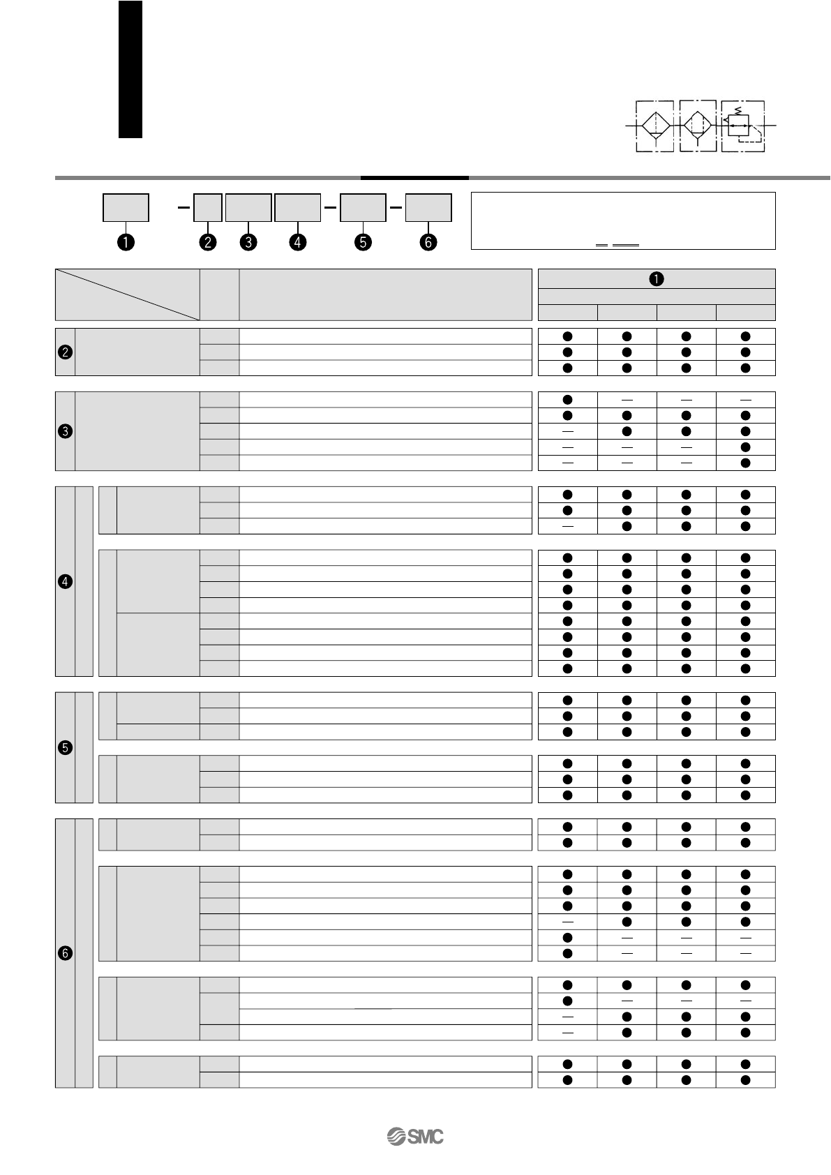
How to Order
• Option/Semi-standard: Select one each for a to j.
•
Option/Attachment/Semi-standard symbol: When more than one
specification is required, indicate in ascending alphanumeric order.
Example) AC30C-F03DE1-SV-16NR
Semi-standard Attachment
Note 3)
Option
AC40CAC20C
Description
Symbol
25 30 4020
Body size
Air
–5 to 60°C (with no freezing)
1.5 MPa
1.0 MPa
0.05 MPa
0.05 to 0.85 MPa
Set pressure + 0.05 MPa [at relief flow rate of 0.1 l/min (ANR)]
AF: 5 µm, AFM: 0.3 µm (99.9% filtered particle size)
Max. 1.0 mg/m
3
(ANR) (≈ 0.8 ppm)
Note 4) Note 5)
Polycarbonate
Relieving type
450
0.88
200
Semi-standard
0.74
Standard
450
0.95
1100
1.76
1100
1.83
Model
Component
Port size
Pressure gauge port size
Note 1)
Fluid
Ambient and fluid temperature
Note 2)
Proof pressure
Maximum operating pressure
Minimum operating pressure
Set pressure range
Relief pressure
Nominal filtration rating
Outlet side oil mist concentration
Rated flow (l/min (ANR))
Note 3)
Bowl material
Bowl guard
Regulator construction
Mass (kg)
Air filter
Mist separator
Regulator
AC40C-06
AF40-06
AFM40-06
AR40-06
3/4
AC40C
AF40
AFM40
AR40
1/4, 3/8, 1/2
AC30C
AF30
AFM30
AR30
1/4, 3/8
AC25C
AF30
AFM30
AR25
1/4, 3/8
AC20C
AF20
AFM20
AR20
1/8, 1/4
1/8 1/4
Note 1) Pressure gauge connection threads are not available for F.R.L. unit with a square embedded type pressure gauge or with a digital pressure switch (AC20C to AC40C).
Note 2) –5 to 50
°C for the products with the digital pressure switch.
Note 3) Conditions: Mist separator inlet pressure: 0.7 MPa; The rated flow varies depending on the inlet pressure. Keep the air flow within the rated flow to prevent an outflow of
lubricant to the outlet side.
Note 4) When the compressor oil mist discharge concentration is 30 mg/m
3
(ANR).
Note 5) Bowl O-ring and other O-rings are slightly lubricated.
Standard Specifications
—
Z
Note 10)
ZA
Note 11)
Pressure unitj
Name plate and pressure gauge in imperial units: MPa
Name plate, caution plate for bowl, and pressure gauge in imperial units: psi, °F
Digital pressure switch: With unit conversion function
—
R
Flow directioni
Flow direction: Left to right
Flow direction: Right to left
Note 1) Drain guide is NPT1/8 (applicable to the AC20C)
and NPT1/4 (applicable to the AC30C to AC40C).
The auto drain port comes with a ø3/8" one-touch
fitting (applicable to the AC30C to AC40C).
Note 2) Drain guide is G1/8 (applicable to the AC20C)
and G1/4 (applicable to the AC30C to AC40C).
Note 3) Option G, M are not assembled and supplied
loose at the time of shipment.
Note 4) The bracket position varies depending on the T-
interface or pressure switch mounting.
Note 5) The regulator is equipped with a backflow function
in this configuration. Additionally, for safety
purposes, please check that the pressure in the
outlet side is turned to the atmospheric pressure
once the pressure in the outlet side is exhausted,
by using a pressure gauge, etc.
Note 6) The only difference from the standard
specifications is the adjusting spring for the
regulator. It does not restrict the setting of 0.2
MPa or more. When the pressure gauge is
attached, a 0.2 MPa pressure gauge will be fitted.
Note 7) Float type auto drain: The combination between C
or D is not available with the drain port option.
Note 8) Without a valve function
Note 9) Metal bowl: The combination of 2 and 8 cannot be
selected with W.
Note 10) For thread type: NPT. This product is for
overseas use only according to the new
Measurement Law. (The SI unit type is provided
for use in Japan.) The digital pressure switch will
be equipped with the unit conversion function,
setting to psi initially.
MPa and psi are shown together on the pressure
unit.
Note 11) For options: E1, E2, E3, E4. This product is for
overseas use only according to the new
Measurement Law. (The SI unit is provided for
use in Japan.)
Note 12)
: For thread type: NPT only
Note 13)
: Select with options: E1, E2, E3, E4.
+
Semi-standard
Note 12) Note 12) Note 12) Note 12)
Note 13) Note 13) Note 13) Note 13)
Air Combination
Series AC20C to AC40C
15