CAT.EUS40-42- D UK Modular F.R.L. Unit New d Roun re p e p ty ssu uge a g e r our l o c ith ow z is n ) e n o le.
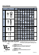
Modular F.R.L. Unit Series AC Improved installation Improved visibility for lubricant drip with graduation for lubricant control Bracket with spacer Retainer Graduation 6 3 5 2 8 SMC 4 7 9 1 Spacer with bracket Lever pin q Attach the component into the fitting of the spacer with bracket. w Lock the lever pin into the retainer. (temporary installation) Embedded pressure gauge is a standard feature.
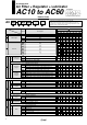
Series Configuration Product Model Air Filter + Regulator + Lubricator AF AR AL Port size M5 1/8 1/4 3/8 1/2 3/4 1 Page AC10 AC20 AC25 AC30 AC40 1 AC40-06 AC50 AC55 AC60 Filter Regulator + Lubricator AW AL AC10A AC20A AC30A AC40A 7 AC40A-06 Air Combination AC50A AC60A Air Filter + Regulator AF AC10B AR AC20B AC25B AC30B AC40B 11 AC40B-06 AC50B AC55B AC60B Air Filter + Mist Separator + Regulator AF AFM AR AC20C AC25C AC30C 15 AC40C AC40C-06 Filter Regulator + Mist Separato
Series Configuration Product AF Model Port size M5 1/8 1/4 3/8 1/2 3/4 1 Page AF10 AF20 Air Filter AF30 AF40 29 AF40-06 AF50 Mist Separator AF60 AFM AFM20 AFM30 AFM40 39 AFM40-06 Micro Mist Separator AFD AFD20 AFD30 AFD40 39 AFD40-06 AR AR10 AR20 Regulator AR25 AR30 AR40 47 AR40-06 AR50 AR60 Regulator with Backflow Function ARK AR20K AR25K AR30K AR40K AR40K-06 AR50K AR60K Features 3 47
Series Configuration Product AL Model Port size M5 1/8 1/4 3/8 1/2 3/4 1 Page AL10 AL20 Lubricator AL30 AL40 59 AL40-06 AL50 AL60 Filter Regulator AW AW10 AW20 AW30 67 AW40 AW40-06 AWK AW20K AW30K AW40K 67 AW40K-06 Mist Separator Regulator AW60K AWM Micro Mist Separator Regulator Filter Regulator with Backflow Function AW60 AWD AWM20 AWM30 79 AWM40 AWD20 AWD30 79 AWD40 Simple Specials System A system designed to respond quickly and easily to your special ordering needs
Air Combination Air Filter + Regulator + Lubricator AC10 to AC60 How to Order AC 30 03 DE Air Filter Description N Note 1) F Note 2) Metric thread (M5) Rc NPT G M5 01 02 03 04 06 10 M5 1/8 1/4 3/8 1/2 3/4 1 + Port size + a Float type auto drain — C D + — Option Note 3) Pressure gauge b Digital pressure switch E G M E1 E2 E3 E4 + c Check valve d Pressure switch — Attachment e T-interface f 3-port valve for residual pressure release — Without attachment Semi-standard g 1
Air Combination Series AC10 to AC60 AC20 Symbol Description Body size 10 Semi-standard i j k Exhaust mechanism 25 30 40 50 55 60 Flow direction + — Pressure unit Without drain cock 3 Note 10) Lubricator with drain cock + — N + — Relieving type Non-relieving type R Flow direction: Left to right Flow direction: Right to left — Name plate and pressure gauge in imperial units: MPa + m 20 — With drain cock Drain guide 1/8 Filter Note 8) J drain port Note 7) Drain guide 1/4 W Not
Series AC10 to AC60 Flow Characteristics (Representative values) AC10 M5 x 0.8 Condition: Inlet pressure 0.7 MPa AC20 0.4 0.3 0.2 0.1 0 0 25 50 75 100 Flow rate (l/min (ANR)) 125 AC30 0.4 0.3 0.2 0.1 0 0 150 Rc3/8 400 0.3 0.2 0.1 0 0 500 1000 Rc1/2 Rc1 0.1 0 0 0.3 0.2 0.1 0 0 1000 2000 0.1 0.2 0.1 0 0 Rc1 2000 4000 6000 8000 0.4 0.3 0.2 0.1 0 2000 0 4000 6000 8000 0.2 Outlet pressure (MPa) Set point Set point 0.2 0 0.2 0.3 0.4 0.5 0.6 0.7 0.8 0.9 0 1.
Air Combination Pressure Characteristics (Representative values) 0.2 0.15 0 AC60 Set point 0.25 0.2 0.15 0 0.2 0.3 0.4 0.5 0.6 0.7 0.8 0.9 0 1.0 Inlet pressure (MPa) Set point 0.25 Outlet pressure (MPa) Outlet pressure (MPa) Set point to AC60 Conditions: Inlet pressure 0.7 MPa, Outlet pressure 0.2 MPa, Flow rate 20 l/min (ANR) AC55 0.25 Outlet pressure (MPa) AC50 Series AC10 0.2 0.15 0 0.2 0.3 0.4 0.5 0.6 0.7 0.8 0.9 1.0 0 0 0.2 0.3 Inlet pressure (MPa) 0.
Series AC10 to AC60 Dimensions AC10, AC20 L Centre of piping Metal bowl with level gauge With drain guide Drain cock with barb fitting B S 1/4 Width across flats 17 Square type pressure gauge P1 P2 A B C E F M5 x 0.8 1/16 87 85 26 — 28 G 35 13 J 0 1/8, 1/4 1/8 126 123 36 — 41.5 60 28.5 1/4, 3/8 1/8 167 153 38 30 55 80 27.5 1/4, 3/8 1/8 167 153 38 30 55 80 1/4, 3/8, 1/2 1/4 220 187 40 38 72.
6
Air Combination Filter Regulator + Lubricator AC10A to AC60A JIS Symbol How to Order AC 30 A 03 DE Filter Regulator • Option/Semi-standard: Select one each for a to l. • Option/Attachment/Semi-standard symbol: When more than one specification is required, indicate in ascending alphanumeric order.
Air Combination Series AC10A to AC60A AC20A AC40A Symbol Description Body size Semi-standard 10 i Lubricator lubricant exhaust port j Exhaust mechanism k Flow direction — 3 + — N + — l Pressure unit 30 40 50 60 Without drain cock Lubricator with drain cock Relieving type Non-relieving type R Flow direction: Left to right Flow direction: Right to left — Name plate and pressure gauge in imperial units: MPa + 20 Z Note 10) Name plate, caution plate for bowl, and pressure gauge i
Series AC10A to AC60A Dimensions AC10A, AC20A AC30A to AC60A (Pressure gauge port size) A M J A M F F OUT H H 1/8 ø10 one-touch Width across flats 14 fitting Metal bowl B S 1/4 Width across flats 17 Square type pressure gauge G J Round type pressure gauge Round type pressure gauge (with colour zone) B Note) C E F K H J H J H J H J 56 108 48 — 28 35 13 0 — — — — ø26 26 — — 83 160 73 — 41.5 60 26 5 28 27 27.8 37.5 ø37.5 63 ø37.
10
Air Combination Air Filter + Regulator AC10B to AC60B Air Filter How to Order AC 30 B 03 DE Description Body size 10 Thread type N Note 1) F Note 2) Metric thread (M5) Rc NPT G M5 01 02 03 04 06 10 M5 1/8 1/4 3/8 1/2 3/4 1 + Port size + a Float type auto drain — C D + — Option Note 3) Pressure gauge b Digital pressure switch M E1 E2 E3 E4 — Without attachment G Attachment + c Pressure switch T-interface 3-port valve for d residual pressure release e Set pressure Without au
Air Combination Series AC10B to AC60B AC20B Symbol Description Body size 10 Exhaust mechanism Semi-standard h i Flow direction — N + — j Pressure unit 20 25 30 40 50 55 60 Relieving type Non-relieving type R Flow direction: Left to right Flow direction: Right to left — Name plate and pressure gauge in imperial units: MPa + AC40B Z Note 10) Name plate, caution plate for bowl, and pressure gauge in imperial units: psi, °F ZA Note 11) Digital pressure switch: With unit conversion
Series AC10B to AC60B Dimensions AC10B, AC20B AC25B to AC60B A 2 x P1 (Port size) O S 1/8 ø10 one-touch Width across flats 14 fitting A B 56 71 B B B B Metal bowl with level gauge With drain guide Drain cock with barb fitting S 1/4 Width across flats 17 Barb fitting Applicable tubing: T0604 Optional specifications Standard specifications P1 P2 M5 x 0.
14
Air Combination Air Filter + Mist Separator + Regulator AC20C to AC40C JIS Symbol Air Filter Mist Separator Regulator How to Order AC 30 C 03 DE Symbol • Option/Semi-standard: Select one each for a to j. • Option/Attachment/Semi-standard symbol: When more than one specification is required, indicate in ascending alphanumeric order.
Air Combination Series AC20C to AC40C AC20C Symbol AC40C Description Body size Semi-standard 20 i Flow direction R Flow direction: Left to right Flow direction: Right to left — Name plate and pressure gauge in imperial units: MPa — + j Pressure unit Z Note 10) Name plate, caution plate for bowl, and pressure gauge in imperial units: psi, °F ZA Note 11) Digital pressure switch: With unit conversion function Note 1) Drain guide is NPT1/8 (applicable to the AC20C) and NPT1/4 (applicable to t
Series AC20C to AC40C Dimensions AC20C AC25C to AC40C-06 P2 (Pressure gauge port size) P2 A (Pressure gauge port size) A N R2 R2 K C Q1 Q1 Q2 V F M J N OUT OUT IN Drain Air Filter B 2 x P1 (Port size) Drain Mist Regulator Separator Square embedded type pressure gauge Digital pressure switch Drain Drain Air Filter Mist Separator J Centre of piping H Centre of piping Centre of piping AC20C O 1/8 ø10 one-touch Width across flats 14 fitting M5 S P1 1/8, 1/4 AC20C 1/4, 3/8
18
Air Combination Filter Regulator + Mist Separator AC20D to AC40D Filter Regulator How to Order AC 30 D 03 DE Symbol Description — N Note 1) F Note 2) Rc NPT G 01 02 03 04 06 1/8 1/4 3/8 1/2 3/4 + Port size + a Float type auto drain — C D + — Option Note 3) Pressure gauge b Digital pressure switch Attachment c 3-port valve for d residual pressure release e Set pressure Without auto drain Float type auto drain (N.C.) Float type auto drain (N.O.
Air Combination Series AC20D to AC40D AC20D Symbol Description AC40D Body size Semistandard 20 — j Pressure unit Note 1) Drain guide is NPT1/8 (applicable to the AC20D) and NPT1/4 (applicable to the AC30D to AC40D). The auto drain port comes with a ø3/8" one-touch fitting (applicable to the AC30D to AC40D). Note 2) Drain guide is G1/8 (applicable to the AC20D) and G1/4 (applicable to the AC30D to AC40D). Note 3) Option G, M are not assembled and supplied loose at the time of shipment.
Series AC20D to AC40D Dimensions AC20D AC30D to AC40D-06 P2 P2 2 x P1 (Port size) (Pressure gauge port size) A J A F M F M Drain Drain V R1 B Drain Drain Filter Regulator Mist Separator AC20D to AC40D-06 Square embedded type pressure gauge Digital pressure switch Round type pressure gauge Round type pressure gauge (with colour zone) J Centre of piping H J H Centre of piping AC20D O 1/8 ø10 one-touch Width across flats 14 fitting M5 S 1/4 Width across flats 17 P1 1/8, 1/4 A
Air Combination Series AC Options/Attachments Type Pressure gauge Note 1) Option Section Options/Attachments Part No. Round type Round type (with colour zone) Square Note 2) embedded type Digital pressure switch Float type auto drain Spacer NPN output/Wiring bottom entry NPN output/Wiring top entry PNP output/Wiring bottom entry PNP output/Wiring top entry Note 5) N.O. N.C.
Series AC Pressure Switch: (S) A compact integrated pressure switch can be easily installed and facilitates the pressure detection of the line. IS1000M 30 JIS Symbol Pressure switch Description Lead wire length Set pressure range Pressure display 0.5 m 0.5 m 0.5 m 0.5 m 3m 3m 3m 3m 0.1 to 0.4 MPa 0.1 to 0.4 MPa 0.1 to 0.6 MPa 0.1 to 0.6 MPa 0.1 to 0.4 MPa 0.1 to 0.4 MPa 0.1 to 0.6 MPa 0.1 to 0.
Attachments Series AC Residual Pressure Release 3 Port Valve: (V) With the use of a 3-port valve for residual pressure release, pressure left in the line can be easily exhausted. 03 JIS Symbol (A) 2 • Semi-standard: Select one each for a to b. • Semi-standard symbol: When more than one specification is required, indicate in ascending alphabetic order.
Series AC Piping Adapter: M5, 1/8, 1/4, 3/8, 1/2, 3/4, 1 Port size Centre of F.R.L. body D A Piping adapter Symbol Port size M5 1/8 1/4 3/8 1/4 3/8 1/2 1/4 3/8 1/2 3/4 E500-06 3/4 E600-06 3/4 E600-10 1 D 14 30 23.
Series AC Spacers/Brackets Accessories Spacer D C Centre of F.R.L. body X Y400 X A B C D Applicable model Y100 Y200 Y300 Y400 Y500 6 3 4 5 5 27 35.5 47 57 61 15 18.5 26 31 33 33 48 59 65 75 AC10, AC10A, AC10B AC20 AC25, AC30 AC40 AC40-06 AC50, AC55, AC60 AC50A, AC60A AC50B, AC55B, AC60B 6 75.5 41 86 X-X 2 Model Y600 RELEASE Y200 B 1 Seal A (Spacer width) Replacement Parts Description Material Seal HNBR Note 2) Part no.
Series AC Mounting Position for Spacer with Bracket Bracket Pressure switch: S T-interface: T 3-port valve for residual pressure: V Check valve: K SUP. SUP OUT IN OUT IN Bracket A1 Attachment Model AC10 AC20 AC25 AC30 AC40 AC40-06 AC50 AC55 AC60 Attachment Model AC10 AC20 AC25 AC30 AC40 AC40-06 AC50 AC55 AC60 A2 K A2 — 43 57 57 75 — — — — A1 — 41.5 55 55 72.5 — — — — A2 — 43 57 57 75 — — — — A3 — 57 74 74 95 — — — — A2 43 57 75 — — — A1 41.5 55 72.5 77.
Modular Type Air Filters Series AF Air Filter Series AF Model AF10 M5 AF20 1/8, 1/4 AF30 1/4, 3/8 AF40 1/4, 3/8, 1/2 AF40-06 Page 29 through to 37 Mist Separator Series AFM Port size Filtration (µm) 5 3/4, 1 AF60 1 AFM20 1/8, 1/4 AFM30 1/4, 3/8 0.3 Page 39 through to 45 Micro Mist Separator Series AFD AFM40-06 1/4, 3/8, 1/2 1/8, 1/4 AFD30 1/4, 3/8 0.
Air Filter AF10 to AF60 JIS Symbol Air Filter Air Filter with Auto Drain AF20 AF40 How to Order AF 30 03 BD • Option/Semi-standard: Select one each for a to f. • Option/Semi-standard symbol: When more than one specification is required, indicate in ascending alphanumeric order. Example) AF30-03BD-2R Made to Order (Refer to page 35 through to 37 for details.
Air Filter Series AF10 to AF60 Standard Specifications Model Port size Fluid Ambient and fluid temperature Proof pressure Maximum operating pressure Nominal filtration rating Drain capacity (cm3) Bowl material Bowl guard Mass (kg) AF10 AF20 AF30 M5 1/8, 1/4 1/4, 3/8 2.5 8 — 0.06 Semi-standard 0.18 AF10 AF20 AF40 AF40-06 1/4, 3/8, 1/2 3/4 Air –5 to 60°C (with no freezing) 1.5 MPa 1.0 MPa 5 µm 25 45 Polycarbonate Standard 0.45 0.49 0.22 AF50 AF60 3/4, 1 1 0.99 1.
Series AF10 to AF60 Flow Characteristics (Representative values) AF20 0 0 200 Flow rate (l/min (ANR)) 4000 2000 6000 0.06 0.04 Pa =0 .5 M Pa P1 =0 .7 MP a P1 4000 Rc1 0.02 0 0 Flow rate (l/min (ANR)) Flow rate (l/min (ANR)) 3000 P1 = a MP a =0 .7 P1 P1 =0 .5 MP Pa 4000 2000 AF50 0.08 0.04 0.3 M 0.1 M Pa 1000 0.1 MP a P1 =0 .3 M Pa P1 =0 P1 .5 M Pa =0 .7 MP a Rc3/4 0.08 0.06 P1 = P1 = .5 MP a =0 .7 MP a =0 .3 M P1 P1 =0 Pressure drop (MPa) 0.02 0.
Air Filter Series AF10 to AF60 Working Principle: Float Type Auto Drain N.O. type: AD38, AD48 N.C. type: AD37, AD47 q Bowl r Valve e Lever w Float t Valve seat i Chamber y Spring u Piston o Housing !0 Seal !1 Drain cock Drain q Bowl r Valve e Lever w Float t Valve seat i Chamber u Piston y Spring o Housing !0 Seal !1 Drain cock Compact auto drain N.C.
Series AF10 to AF60 Construction AF10, AF20 IN AF50, AF60 AF30 to AF40-06 IN OUT OUT IN OUT q q r r q w e w e y t t w r e Drain t Drain Drain Component Parts No. Description 1 Body 6 Housing Material Model Zinc die-cast AF10, AF20 Color Aluminum die-cast AF30 to AF60 Aluminum die-cast AF50, AF60 Platinum silver Platinum silver Replacement Parts No. Description Material Part no.
Air Filter Series AF10 to AF60 Dimensions AF10, AF20 AF50, AF60 Bracket (Option) U Bracket (Option) S IN J OUT T M D C Q D T N R M V J N U S R OUT OUT IN s Clearance for maintenance o OUT G Drain A 2xP (Port size) M D T N Bracket (Option) S V IN C Q R U B AF30 to AF40-06 J C Q V B 2xP (Port size) OUT 2xP (Port size) Drain Clearance for maintenance G Drain AF20 O S Metal bowl with level gauge With drain guide Drain cock with barb fitting B 1/8 ø10 on
Air Filter AF10 to AF60 Made to Order Please contact SMC for detailed dimensions, specifications, and lead times. q Special Temperature Environment w High Pressure Special materials are used in the manufacturing of seals and resin parts to allow them to withstand various temperature conditions in cold or tropical (hot) climates. Strong materials are used in the manufacturing of air filters intended for high pressure operation. Specifications Specifications Made-to-order no.
Air Filter Series AF10 to AF60 e Long Bowl Drain capacity is greater than that of standard models. Applicable Model/Drain Capacity Model Port size AF10 AF20 AF30 AF40 AF40-06 AF50 AF60 M5 1/8, 1/4 1/4, 3/8 1/4, 3/8, 1/2 3/4 3/4, 1 1 9 19 43 Drain capacity (cm3) 88 Note) Please consult SMC for dimensions. AF 30 03 X64 Long bowl • Semi-standard: Select one each for a to d.
Air Filter AF30 to AF60 Made to Order Please contact SMC for detailed dimensions, specifications, and lead times. r With Element Service Indicator Clogging status of elements can be checked visually. Applicable Model Model AF30 AF40 AF40-06 AF50 AF60 Port size 1/4, 3/8 1/4, 3/8, 1/2 3/4 3/4, 1 1 03 AF 30 X2141 With element service indicator A special body type is required to mount the clogging checker. It cannot be mounted on a standard body.
38
Mist Separator AFM20 to AFM40 Micro Mist Separator AFD20 to AFD40 JIS Symbol Mist Separator Micro Mist Separator • Series AFM Nominal filtration rating: 0.3 µm • Series AFD Nominal filtration rating: 0.01 µm How to Order AFM 30 03 BD AFD 30 03 BD AFM20, AFD20 AFM40, AFD40 • Option/Semi-standard: Select one each for a to f. • Option/Semi-standard symbol: When more than one specification is required, indicate in ascending alphanumeric order.
to AFM40 Micro Mist Separator Series AFD20 to AFD40 Mist Separator Series AFM20 Standard Specifications Model Port size Fluid Ambient and fluid temperature Proof pressure Maximum operating pressure Minimum operating pressure Nominal filtration rating Outlet side oil mist concentration Rated flow (l/min (ANR)) Note 1) AFM20 to AFM40-06 AFD20 to AFD40-06 AFM20 to AFM40-06 AFD20 to AFD40-06 AFM20 to AFM40-06 AFD20 to AFD40-06 Drain capacity (cm3) Bowl material Bowl guard Mass (kg) AFM20 AFD20 AFM30 AFD3
Series AFM20 to AFM40 Series AFD20 to AFD40 : When saturated with oil : Initial state Flow Characteristics (Representative values) AFM20 AFM30 0.04 = .5 M =0 P1 M P1 .7 =0 M 0.02 0.01 0 0 .3 =0 P1 50 a MP P1 a P .5 M =0 P1 = 100 Pa .7 M 0 150 0.03 P P 3M . P1 =0 = Pa = P1 M 0.5 P1 P1 = M 0.3 P1 .5 =0 a MP P1 = 50 Pa 7M = 0. 0.02 Pa Pa 7M 0. P1 = 100 200 a MP .5 P1 =0 P1 0.04 Pa 0.7 M Pressure drop (MPa) Pressure drop (MPa) P1 M 0.
to AFM40 Micro Mist Separator Series AFD20 to AFD40 Mist Separator Series AFM20 Construction AFM20 AFD20 IN OUT Float type auto drain (N.C.) q e w r Drain M5 x 0.8 AFM30 to AFM40-06 AFD30 to AFD40-06 IN Float type auto drain OUT N.O. N.C. q e w r Drain ø10 one-touch fitting ø10 one-touch fitting Component Parts No. 1 Description Body Material Model Zinc die-cast AFM20, AFD20 Colour Aluminum die-cast AFM30 to AFM40-06, AFD30 to AFD40-06 Platinum silver Replacement Parts Part no.
Series AFM20 to AFM40 Series AFD20 to AFD40 Dimensions D T Bracket (Option) U N S R M J Q V AFM20 AFD20 OUT C IN OUT B 2xP (Port size) s Clearance for maintenance o G Drain A U Bracket (Option) T N S R D V M OUT IN C J Q AFM30 to AFM40-06 AFD30 to AFD40-06 E Clearance for maintenance 2xP (Port size) Drain A O S 1/8 ø10 one-touch Width across flats 14 fitting M5 P 1/8, 1/4 AFM20/AFD20 1/4, 3/8 AFM30/AFD30 1/4, 3/8, 1/2 AFM40/AFD40 3/4 AFM40-06/AFD40-06 43 B B
Mist Separator AFM20 to AFM40 Micro Mist Separator AFD20 to AFD40 Made to Order Please contact SMC for detailed dimensions, specifications, and lead times. q Long Bowl Drain capacity is greater than that of standard models. Applicable Model/Drain Capacity AFM20, AFD20 AFM30, AFD30 AFM40, AFD40 AFM40-06, AFD40-06 Model Port size 1/8, 1/4 1/4, 3/8 19 43 Drain capacity (cm3) 1/4, 3/8, 1/2 3/4 88 Note) Please consult SMC for dimensions.
Mist Separator AFM30 to AFM40 Micro Mist Separator AFD30 to AFD40 Made to Order Please contact SMC for detailed dimensions, specifications, and lead times. w With Element Service Indicator Clogging status of elements can be checked visually. Applicable Model Model AFM30, AFD30 AFM40, AFD40 AFM40-06, AFD40-06 Port size 1/4, 3/8 1/4, 3/8, 1/2 3/4 AFM 30 03 X2141 AFD 30 03 X2141 With element service indicator A special body type is required to mount the clogging checker.
Modular Type Regulators Series AR Regulator Series AR Model AR10 M5 AR20 1/8, 1/4 AR25 1/4, 3/8 AR30 1/4, 3/8 AR40 1/4, 3/8, 1/2 AR40-06 Page 47 through to 56 Regulator with Backflow Function Series ARK 3/4 AR50 3/4, 1 AR60 1 AR20K 1/8, 1/4 AR25K 1/4, 3/8 AR30K 1/4, 3/8 AR40K 1/4, 3/8, 1/2 AR40K-06 Page 47 through to 56 Port size Options Bracket Square embedded type pressure gauge (except the AR10) Round type pressure gauge Digital pressure switch (except the AR10) Panel mo
Regulator AR10 to AR60 JIS Symbol Regulator Regulator with Backflow Function Regulator with Backflow Function AR20K to AR60K • With the backflow function it incorporates a mechanism to exhaust the air pressure in the outlet side reliably and quickly.
to AR60 Regulator with Backflow Function Series AR20K to AR60K Regulator Series AR10 AR20, AR20K Symbol Description Body size 10 c Set pressure d Exhaust mechanism — Note 5) AR40, AR40K 20 25 30 40 50 60 0.05 to 0.85 MPa setting 1 Note 6) 0.02 to 0.
Series AR10 to AR60 Series AR20K to AR60K Options/Part No. Model Option AR10 AR20(K) AR25(K) AR30(K) AR40(K) AR40(K)-06 AR50(K) AR60(K) AR50P-270AS Note 2) AR40P-270AS Bracket assembly AR10P-270AS AR20P-270AS AR25P-270AS AR30P-270AS AR40P-260S Set nut AR10P-260S AR20P-260S AR25P-260S AR30P-260S — Note 3) — Note 3) Note 4) G36-10-01 Standard G46-10-02 G27-10-R1 Round type G36-2-01 0.02 to 0.
to AR60 Regulator with Backflow Function Series AR20K to AR60K Regulator Series AR10 Flow Characteristics (Representative values) M5 AR30(K) 0.5 0.5 0.5 0.4 0.3 0.2 Outlet pressure (MPa) 0.6 0 0 0.4 0.3 0.2 0.1 25 50 75 100 125 AR20(K) 0.4 0.3 0.2 500 1000 0 1500 AR40(K) Rc1/2 AR60(K) 0.5 0.5 0.5 0.3 0.2 0.1 0.4 0.3 0.2 200 400 600 0 0 800 AR25(K) 1000 2000 3000 Flow rate (l/min (ANR)) Rc3/8 AR40(K)-06 0.6 0.5 0.5 Outlet pressure (MPa) 0.6 0.4 0.
Series AR10 to AR60 Series AR20K to AR60K Pressure Characteristics (Representative values) Conditions: Inlet pressure 0.7 MPa, Outlet pressure 0.2 MPa, Flow rate 20 l/min (ANR) AR30(K) AR10 0.3 AR50(K) 0.25 0.2 0.15 Outlet pressure (MPa) 0.25 Outlet pressure (MPa) Outlet pressure (MPa) 0.25 Set point Set point 0.2 0.2 0.3 0.4 0.5 0.6 0.7 0.8 0.9 0 0 1 0.2 0.3 AR20(K) 0.8 0.9 0 0 1 0.2 0.3 0.4 0.5 0.6 0.7 0.8 0.9 Set point 0.2 0 0 1 0.3 0.4 0.5 0.6 0.7 0.
Series AR10 to AR60 Regulator with Backflow Function Series AR20K to AR60K Regulator Construction AR10 e t IN OUT r q AR20(K), AR25(K) q t e IN OUT r w w AR30(K), AR40(K) q t e IN OUT r w AR50(K), AR60(K) t q e IN OUT r w AR20K to AR60K (Regulator with Backflow Function) A-A A 1 OUT y 2 IN SMC A Component Parts No.
Series AR10 to AR60 Series AR20K to AR60K Working Principle (Regulator with Backflow Function) AR10 w w IN OUT IN OUT (Inlet pressure) (Outlet pressure) (Inlet pressure) (Outlet pressure) q q Figure 1 Figure 2 When the inlet pressure is higher than the regulating pressure, the check valve operates as a normal regulator (Figure 1). When the inlet pressure is shut off and exhausted, any inlet pressure applied to the valve q will be lost.
to AR60 Regulator with Backflow Function Series AR20K to AR60K Regulator Series AR10 Dimensions AR10, AR20(K) to AR40(K)-06 2 x P1 (Port size) Panel fitting dimension A K C W Y OUT IN OUT IN Q B V Z Plate thickness AR10, AR20(K) to AR30(K): Max. 3.5 AR40(K): Max.
Regulator AR20 to AR60 Made to Order Please contact SMC for detailed dimensions, specifications, and lead times. AR30-03-X425 q Special Temperature Environment w High Pressure Special materials are used in the manufacturing of seals and resin parts to allow them to withstand various temperature conditions in cold or tropical (hot) climates. Strong materials are used in the manufacturing of air filters intended for high pressure operation.
Regulator AR10 to AR60 Regulator with Backflow Function AR20K to AR60K Made to Order Please contact SMC for detailed dimensions, specifications, and lead times. e 0.4 MPa Setting The maximum set pressure is 0.4 MPa. When a pressure gauge is included, the display will show a range from 0 to 0.4 MPa. Specifications Proof pressure Maximum operating pressure Set pressure range 1.5 MPa 1.0 MPa 0.05 to 0.
57
Modular Type Lubricators Series AL Lubricator Series AL Model AL10 M5 AL20 1/8, 1/4 AL30 1/4, 3/8 AL40 1/4, 3/8, 1/2 AL40-06 Page 59 through to 64 Port size Option Bracket 3/4 AL50 3/4, 1 AL60 1 58
Lubricator AL10 to AL60 JIS Symbol Lubricator AL20 How to Order AL 30 03 B Symbol • Option/Semi-standard: Select one each for a to d. • Option/Semi-standard symbol: When more than one specification is required, indicate in ascending alphanumeric order.
Lubricator Series AL10 to AL60 Standard Specifications Model Port size Fluid Proof pressure Maximum operating pressure Ambient and fluid temperature AL10 AL20 AL30 M5 1/8, 1/4 1/4, 3/8 4 15 7 25 — 0.07 Semi-standard 0.20 Minimum dripping flow rate Note) [l/min (ANR)] Oil capacity (cm3) Recommended lubricant Bowl material Bowl guard Mass (kg) AL40 AL40-06 1/4, 3/8, 1/2 3/4 Air 1.5 MPa 1.
Series AL10 to AL60 Working Principle: AL10 Type Flow Characteristics (Representative values) AL10 AL40-06 0.04 Pa MP a Needle Section AA’ P1 P1 = =0 .7 0.5 M MPa 0.3 0.06 P1 = MPa Pressure drop (MPa) 0.06 0.08 P1 = 0.1 .0 tur 1.5 Open 2 Ope n Rc3/4 0.1 n turn rn 1.0 tu rn 0.5 tu Op e n 0.08 Open Needle fu lly opened 0.1 Pressure drop (MPa) M5 0.04 0.02 0.02 Conditions: P1 = 0.
Lubricator Series AL10 to AL60 Construction AL10 AL20 w w q IN OUT IN OUT y r u y u IN e q t AL30, AL40 AL50, AL60 w qe t w qe t OUT IN OUT y r u r i y u Component Parts No. Description 1 Body 8 Housing Material Model Zinc die-cast AL10, AL20 Colour Aluminum die-cast AL30 to AL60 Aluminum die-cast AL50, AL60 Platinum silver Platinum silver Replacement Parts No. Description Material Part no.
Series AL10 to AL60 J M D B Q 2xP (Port size) S OUT IN OUT B OUT IN Bracket (Option) C A OUT T N U C AL20 AL10 R Dimensions G A AL30, AL40 AL50, AL60 M J D S R C C OUT IN T N U Q V S Bracket (Option) Q U T N Bracket (Option) R M D J Clearance for maintenance G Clearance for maintenance 2xP (Port size) OUT IN OUT B OUT 2xP (Port size) Clearance for maintenance A A Metal bowl with drain cock & level gauge Drain cock with barb fitting B Metal bowl wi
Lubricator Series AL10 to AL60 Dimensions Semi-standard specifications: 1000 cm3 tank 106 2xP (Port size) 90 A 106 70 66 Bracket (Option) 13 C V Q 11 3.
65
Modular Type Filter Regulators Series AW Filter Regulator Series AW Model AW10 M5 AW20 1/8, 1/4 AW30 1/4, 3/8 AW40 1/4, 3/8, 1/2 AW40-06 Page 67 through to 78 Filter Regulator with Backflow Function Series AWK AW60 3/4 3/4, 1 AW20K 1/8, 1/4 AW30K 1/4, 3/8 AW40K 1/4, 3/8, 1/2 AW40K-06 Options Port size 3/4 Bracket Float type auto drain Page 67 through to 78 Mist Separator Regulator Series AWM AW60K 3/4, 1 AWM20 1/8, 1/4 Square embedded type pressure gauge (except the AW10) Rou
Filter Regulator AW10 to AW60 JIS Symbol Filter Regulator with Backflow Function Filter Regulator Filter Regulator with Backflow Function AW20K to AW60K • Integrated filter and regulator units save space and require less piping. • With the backflow function it incorporates a mechanism to exhaust the air pressure in the outlet side reliably and quickly.
to AW60 Filter Regulator with Backflow Function Series AW20K to AW60K Filter Regulator Series AW10 AW20, AW20K Symbol — f Drain port Note 9) J Note 10) Semi-standard W Note 11) + g h Exhaust mechanism Flow direction — N + Pressure unit Body size 10 20 30 40 60 Note 14) Note 14) Note 14) Note 14) Note 14) Note 15) Note 15) Note 15) Note 15) With drain cock Drain guide 1/8 Drain guide 1/4 Drain cock with barb fitting: For ø6 x ø4 nylon tube Relieving type Non-relieving type R F
Series AW10 to AW60 Series AW20K to AW60K Options/Part No. Model Optional specifications AW10(K) AW20(K) AW30(K) AW40(K) AW40(K)-06 AW60(K) AR10P-270AS AW20P-270AS AR30P-270AS AR40P-270AS AW60P-270AS Note 6) AR10P-260S AR20P-260S AR30P-260S AR40P-260S — Note 7) G27-10-R1 Standard G36-10-01 G46-10-02 Round type Note 2) 0.02 to 0.2 MPa setting G27-10-R1 Note 3) G36-2-01 G46-2-02 — Standard G36-10-01-L G46-10-02-L Round type Note 2) Pressure (with colour zone) 0.02 to 0.
Series AW10 to AW60 Series AW20K to AW60K Specific Product Precautions Be sure to read this before handling. Refer to “Precautions for Handling Pneumatic Devices” (M-03-E3A) for Safety Instructions and F.R.L. Units Precautions. Selection Warning 1. Residual pressure disposal (outlet pressure removal) is not possible for the AW20 to AW60 even though the inlet pressure is exhausted. When the residual pressure disposal is performed, use the filter regulator with backflow function (AW20K to AW60K).
Series AW10 to AW60 Series AW20K to AW60K Flow Characteristics (Representative values) M5 AW30(K) 0.5 0.5 0.5 0.4 0.3 0.2 Outlet pressure (MPa) 0.6 0 0.4 0.3 0.2 0 25 50 75 100 Flow rate (l/min (ANR)) 125 0 150 Rc1/4 0 500 1000 0.2 Rc1/2 0.5 0.5 0.3 0.2 Outlet pressure (MPa) 0.5 Outlet pressure (MPa) 0.6 0.4 0.3 0.2 0.1 0 200 400 600 0 800 Flow rate (l/min (ANR)) 0 2000 1000 0.2 0.15 0 0 0.3 0.4 0.5 0.6 0.7 0.8 0.9 0.2 0 1 0 0.2 0.3 0.5 0.
to AW60 Filter Regulator with Backflow Function Series AW20K to AW60K Filter Regulator Series AW10 Construction AW60(K) AW30(K), AW40(K) AW10 IN w w w y y q q OUT IN y q OUT IN OUT r u u u t r t r i i e Drain AW20(K) t w IN i y Drain q AW20K to AW60K (Filter Regulator with Backflow Function) OUT u r o A-A A Drain t i P SH K SMC U OC t o L A Drain Component Parts No.
Series AW10 to AW60 Series AW20K to AW60K Working Principle (Filter Regulator with Backflow Function) AW10 q IN q IN OUT (Outlet pressure) (Inlet pressure) OUT (Outlet pressure) (Inlet pressure) w w When the inlet pressure is higher than the regulating pressure, the check valve operates as a normal regulator (Figure 1). When the inlet pressure is shut off and exhausted, any inlet pressure applied to valve q will be lost. The force for seating valve q is the valve spring w force only.
to AW60 Filter Regulator with Backflow Function Series AW20K to AW60K Filter Regulator Series AW10 Dimensions Q S B Bracket Y S B Plate thickness AW30(K): Max. 3.5 AW40(K): Max.
Filter Regulator AW20 to AW60 Made to Order Please contact SMC for detailed dimensions, specifications, and lead times. q Special Temperature Environment Special materials are used in the manufacturing of seals and resin parts to allow them to withstand various temperature conditions in cold or tropical (hot) climates. Specifications -X430 Made-to-order part no.
Filter Regulator Series AW20 to AW60 w High Pressure Strong materials are used in the manufacturing of air filters intended for high pressure operation. Also, construction modification allows a wider regulating pressure range. Specifications -X425 Made-to-order part no. Proof pressure (MPa) 3.0 Maximum operating pressure (MPa) 2.0 Set pressure range (MPa) 0.1 to 1.
Filter Regulator AW10 to AW60 Filter Regulator with Backflow Function AW20K to AW60K Made to Order Please contact SMC for detailed dimensions, specifications, and lead times. e 0.4 MPa Setting r Long Bowl The maximum set pressure is 0.4 MPa. When a pressure gauge is included, the display will show a range from 0 to 0.4 MPa. Drain capacity is greater than that of standard models.
to AW60 Filter Regulator with Backflow Function Series AW20K to AW60K Filter Regulator Series AW10 0.
Mist Separator Regulator AWM20 to AWM40 JIS Symbol Micro Mist Separator Regulator Mist Separator Regulator Micro Mist Separator Regulator AWD20 to AWD40 • The AWM series is made up of a regulator and a mist separator to provide optimum results in applications such as clean air blow operations. (Nominal filtration rating: 0.3 µm) • The AWD series is made up of a regulator and a micro mist separator to provide optimum results in applications such as ultraclean air blow operations.
to AWM40 Micro Mist Separator Regulator Series AWD20 to AWD40 Mist Separator Regulator Series AWM20 AWM20, AWD20 Symbol Description Body size 20 Exhaust mechanism Semi-standard g h Flow direction Pressure unit 30 40 Relieving type Non-relieving type — N + R Flow direction: Left to right Flow direction: Right to left — Name plate, caution plate for bowl, and pressure gauge in imperial units: MPa — + i AWM40, AWD40 Z Note 11) Name plate, caution plate for bowl, and pressure gauge in im
Series AWM20 to AWM40 Series AWD20 to AWD40 Options/Part No. Model Optional specifications AWM20 AWD20 Bracket assembly Note 1) Set nut Round type Note 2) Pressure gauge Round type Note 2) (with colour zone) Square embedded type Note 3) Standard 0.02 to 0.2 MPa setting Standard 0.02 to 0.2 MPa setting Standard 0.02 to 0.
Series AWM20 to AWM40 Series AWD20 to AWD40 Specific Product Precautions Be sure to read this before handling. Refer to “Precautions for Handling Pneumatic Devices” (M-03-E3A) for Safety Instructions and F.R.L. Units Precautions. Selection Mounting and Adjustment 1. Residual pressure release (outlet pressure release) is not complete by releasing inlet pressure. Please contact SMC regarding residual pressure release. 1.
Series AWM20 to AWM40 Series AWD20 to AWD40 Flow Characteristics (Representative values) AWM20 Rc1/4 AWM30 Rc3/8 0.4 0.3 0.2 0.1 0.5 0.4 0.3 0.2 0.1 50 0 100 0 150 Rc1/4 100 0 0.4 0.3 0.2 0.1 Rc3/8 50 0.4 0.3 0.2 100 0 0.25 0.25 0.20 0.15 0.9 0.20 0.15 0.2 0.3 0.5 0.6 0.7 0.8 0.9 0.15 0.5 0.6 0.7 0.8 0.9 1 400 500 0.20 0.15 0.2 0.3 0.4 0.5 0.6 0.7 0.8 0.9 1 Inlet pressure (MPa) AWD40 0.25 Set point 0.20 0.
to AWM40 Micro Mist Separator Regulator Series AWD20 to AWD40 Mist Separator Regulator Series AWM20 Construction AWM20 AWD20 AWM30, AWM40 AWD30, AWD40 w t w q t q OUT IN IN e OUT y y r u e r u Drain Drain Component Parts No.
Series AWM20 to AWM40 Series AWD20 to AWD40 Dimensions J Panel fitting dimension U Y Bracket (Option) B Plate thickness AWM20, AWD20: Max. 3.
86
Mist Separator Regulator AWM20 to AWM40 Micro Mist Separator Regulator AWD20 to AWD40 Made to Order Please contact SMC for detailed dimensions, specifications, and lead times. q 0.4 MPa Setting w Long Bowl The maximum set pressure is 0.4 MPa. When a pressure gauge is included, the display will show a range from 0 to 0.4 MPa. Drain capacity is greater than that of standard models. Specifications Applicable Model/Drain Capacity Proof pressure Maximum operating pressure Set pressure range 1.5 MPa 1.
to AWM40 Micro Mist Separator Regulator Series AWD20 to AWD40 Mist Separator Regulator Series AWM20 0.4 MPa Setting Symbol d — Note 6) Set pressure 1 Note 7) + — Semi-standard e 2 6 8 C 6C Bowl + f Note 8) Drain port — J Note 9) W Note 10) g Exhaust mechanism h Flow direction + — N + — Pressure unit Body size Body size 20 30 40 20 30 40 Note 13) Note 13) Note 13) Note 13) Note 13) Note 13) Note 14) Note 14) Note 14) Note 14) Note 14) Note 14) 0.05 to 0.
Option Digital Pressure Switch ISE35 N 25 M L A Applicable Series Symbol N Description Wiring bottom entry Electrical entry AC20, AC25, AC30, AC40, AC50, AC55, AC60 AC20A, AC30A, AC40A, AC50A, AC60A AC20B, AC25B, AC30B, AC40B, AC50B, AC55B, AC60B AC20C, AC25C, AC30C, AC40C AC20D, AC30D, AC40D AR20(K), AR25(K), AR30(K), AR40(K), Regulator AR50(K), AR60(K) Filter regulator AW20(K), AW30(K), AW40(K), AW60(K) Mist separator regulator AWM20, AWM30, AWM40 F.R.L.
Option Knob Cover Prevents careless knob operation. Part no. Lock cover AR20P-580AS Applicable model AC20, AR20(K), AW20(K). AWM20, AWD20 AR25P-580AS AC25, AR25(K) AC30, AR30(K), AW3(K), AR30P-580AS AWM30, AWD30 Keyhole dia.
Safety Instructions These safety instructions are intended to prevent hazardous situations and/or equipment damage. These instructions indicate the level of potential hazard with the labels of “Caution,” “Warning” or “Danger.” They are all important notes for safety and must be followed in addition to International Standards (ISO/IEC), Japan Industrial Standards (JIS)∗1) and other safety regulations∗2). ∗ 1) ISO 4414: Pneumatic fluid power – General rules relating to systems.
EUROPEAN SUBSIDIARIES: Austria SMC Pneumatik GmbH (Austria). Girakstrasse 8, A-2100 Korneuburg Phone: +43 2262-622800, Fax: +43 2262-62285 E-mail: office@smc.at http://www.smc.at France SMC Pneumatique, S.A. 1, Boulevard de Strasbourg, Parc Gustave Eiffel Bussy Saint Georges F-77607 Marne La Vallee Cedex 3 Phone: +33 (0)1-6476 1000, Fax: +33 (0)1-6476 1010 E-mail: contact@smc-france.fr http://www.smc-france.