
Datasheet
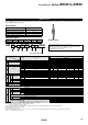
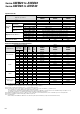
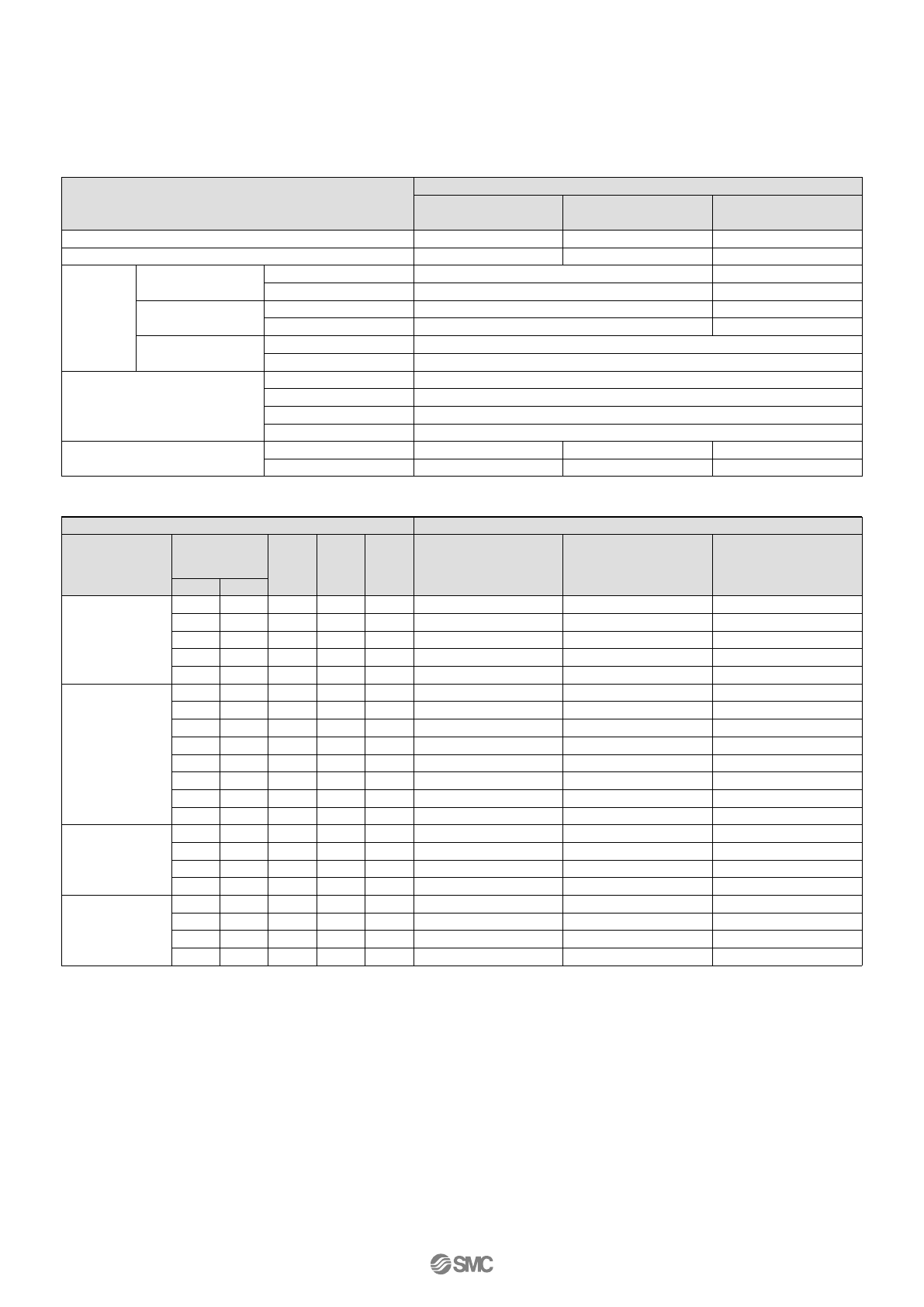
Options/Part No.
Model
Optional specifications
Bracket assembly
Note 1)
Set nut
Pressure
gauge
Digital pressure switch
Note 4)
Float type auto drain
Note 5) Note 6)
Round type
Note 2)
Standard
0.02 to 0.2 MPa setting
Standard
0.02 to 0.2 MPa setting
Standard
0.02 to 0.2 MPa setting
N.C.
N.O.
NPN output / Wiring bottom entry
NPN output / Wiring top entry
PNP output / Wiring bottom entry
PNP output / Wiring top entry
Round type
Note 2)
(with colour zone)
Square embedded
type
Note 3)
AWM20
AWD20
AWM30
AWD30
AW20P-270AS
AR20P-260S
AD27
—
G36-10-01
G36-2-01
G36-10-01-L
G36-2-01-L
AR30P-270AS
AR30P-260S
GC3-10AS [GC3P-010AS (Pressure gauge cover only)]
GC3-2AS [GC3P-010AS (Pressure gauge cover only)]
ISE35-N-25-MLA [ISE35-N-25-M (Switch body only)]
ISE35-R-25-MLA [ISE35-R-25-M (Switch body only)]
ISE35-N-65-MLA [ISE35-N-65-M (Switch body only)]
ISE35-R-65-MLA [ISE35-R-65-M (Switch body only)]
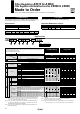
AD37
AD38
AR40P-270AS
AR40P-260S
G46-10-02
G46-2-02
G46-10-02-L
G46-2-02-L
AD47
AD48
AWM40
AWD40
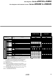
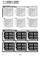
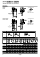
Semi-standard/Bowl Assembly Part No.
Note 1) Assembly includes a bracket and set nuts
Note 2)
in part numbers for a round pressure gauge indicates a type of connection thread. No indication is necessary for R; however, indicate N for NPT. Please contact SMC
regarding the connection thread NPT and pressure gauge supply for psi unit specifications.
Note 3) Includes one O-ring and 2 mounting screws. [ ]: Pressure gauge cover only
Note 4) Lead wire with connector (2 m), adapter, lock pin, O-ring (1 pc.), mounting screw (2 pcs.) are attached. [ ]: Switch body only.
Also, regarding how to order the digital pressure switch, please refer to page 89.
A separate pressure switch adapter assembly (AW60P-310AS) is required only for AW60(K). For mounting, please use the included
mounting screws (M3 x 0.5 x 14).
The mounting screw (M3 x 0.5 x 7) attached to the digital pressure switch assembly will not be required.
Note 5) Minimum operating pressure: N.O. type–0.1 MPa; N.C. type–0.1 MPa (AD27) and 0.15 MPa (AD37/47). Please contact SMC for psi and °F unit specifications.
Note 6) Please consult SMC for details on drain piping to fit NPT or G port sizes.
Note) • Including O-ring.
• Bowl assembly for the AWM30/40, AWD30/40 comes with a bowl guard (steel band material). (except when the bowl material is metal)
—
—
—
—
—
—
—
—
—
—
—
—
—
—
—
—
—
—
—
—
—
—
—
—
—
—
—
—
—
—
—
—
—
—
—
—
—
—
—
—
—
—
—
—
—
—
—
—
—
—
—
—
—
—
—
—
—
—
—
—
—
—
—
—
—
—
—
—
—
—
—
—
—
—
—
—
—
—
—
—
—
—
—
N.C. N.O.
Model
Semi-standard
specifications
With
bowl
guard
With
barb
fitting
Bowl material
Polycarbonate
Nylon
Metal
Metal bowl with
level gauge
AWM30
AWD30
AWM20
AWD20
C2SF-C
AD27-C
C2SF-J
—
C2SF-CJ
C2SF-6
C2SF-6C
AD27-6
—
AD27-6C
C2SF-6J
—
C2SF-6CJ
C2SF-2
AD27-2
—
C2SF-2J
—
—
—
—
—
—
C3SF-J
C3SF-W
—
C3SF-6
—
AD37-6
AD38-6
—
C3SF-6J
C3SF-6W
—
C3SF-2
AD37-2
AD38-2
C3SF-2J
C3LF-8
AD37-8
AD38-8
C3LF-8J
—
—
C4SF-J
C4SF-W
—
C4SF-6
—
AD47-6
AD48-6
—
C4SF-6J
C4SF-6W
—
C4SF-2
AD47-2
AD48-2
C4SF-2J
C4LF-8
AD47-8
AD48-8
C4LF-8J
AWM40
AWD40
With
drain
guide
Note 6)
Float type
auto drain
Note 5) Note 6)
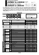
Series AWM20 to AWM40
Series AWD20 to AWD40
Orange mark
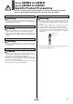
Mounting and Adjustment
1. Be sure to unlock the knob before adjusting the pressure and
lock it after setting the pressure. Failure to follow this procedu-
re can cause damage to the knob and the outlet pressure may
fluctuate.
• Pull the pressure regulator knob to unlock. (You can visually
verify this with the "orange mark" that appears in the gap.)
• Push the pressure regulator knob to lock. When the knob is
not easily locked, turn it left and right a little and then push it
(when the knob
is locked, the "orange mark", i.e., the gap will
disappear).
2.
A knob cover is available to prevent careless operation of the
knob. Refer to page 90 for details.
Warning
Selection
1. Residual pressure release (outlet pressure release) is not com-
plete by releasing inlet pressure. Please contact SMC regar-
ding residual pressure release.
Warning
Maintenance
1. Replace the element every 2 years or when the pressure drop
becomes 0.1 MPa, whichever comes first, to prevent damage
to the element.
Warning
Air Supply
1. Install an air filter (AF series) as a pre-filter on the inlet side of
the mist separator regulator to prevent premature clogging.
2. Install a mist separator (AFM series) as a pre-filter on the inlet
side of the micro mist separator regulator to prevent premature
clogging.
Caution
Mounting and Adjustment
1. Set the regulator while verifying the displayed values of the in-
let and outlet pressure gauges. Turning the regulator knob ex-
cessively can cause damage to the internal parts.
2. The pressure gauge included with regulators for 0.02 to 0.2
MPa setting is for up to 0.2 MPa use only. Exceeding 0.2 MPa
of pressure can damage the gauge.
3. Do not use tools on the pressure regulator knob as this may
cause damage. It must be operated manually.
Caution
Series AWM20 to AWM40
Series AWD20 to AWD40
Specific Product Precautions
Be sure to read this before handling. Refer to “Precautions for Handling Pneumatic
Devices” (M-03-E3A) for Safety Instructions and F.R.L. Units Precautions.
81