Doc. no.
Contents Safety Instructions P2 1. Product specifications P4 1-1. Specifications 1-2. Theoretical output 1-3. Spring reaction force 1-4. Allowable kinetic energy 1-5. Allowable lateral load 2. Mounting・Installation P6 2-1. Design/Selection 2-2. Mounting 2-3. Piping 2-4. Lubrication 2-5. Air supply 2-6. Operating environment 2-7. Maintenance 3. Construction・Description P13 4. Dimensions P14 4-1. Dimensions 4-2. Dimensions of accessories 5.
Safety Instructions These safety instructions are intended to prevent hazardous situations and/or equipment damage. These instructions indicate the level of potential hazard with the labels of “Caution,” “Warning” or “Danger.” They are all important notes for safety and must be followed in addition to International Standards (ISO/IEC)*1) , and other safety regulations. *1) ISO 4414: Pneumatic fluid power -- General rules relating to systems.
Safety Instructions Caution The product is provided for use in manufacturing industries. The product herein described is basically provided for peaceful use in manufacturing industries. If considering using the product in other industries, consult SMC beforehand and exchange specifications or a contract if necessary. If anything is unclear, contact your nearest sales branch.
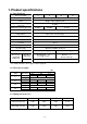
1. Product specifications 1-1. Specifications Bore size (mm) 4 6 10 16 Standard stroke (mm) 5、10、15 Action Maximum operating pressure Minimum operating pressure Single acting, Spring return 0.7MPa 0.3MPa 0.2MPa 0.15Pa Proof pressure Ambient and fluid temperature Lubrication 1MPa -10 to 70oC(No freezing) Piston speed 50 to 500mm/sec Cushion None Not required(Non-lube) +1.
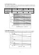
1-4. Allowable kinetic energy When driving an inertial load, operate a cylinder with kinetic energy within the allowable value. The range in the chart below that is delineated by bold solid lines indicates the relation between load mass and maximum driving speeds. Bore size (mm) 4 10 16 8X10⁻³ 19X10-3 50 to 500 0.5X10⁻³ 3X10⁻³ Load mass (kg) Piston speed (mm/sec) Allowable kinetic energy (J) 6 Maximum speed V (mm/sec) 1-5.
2. Mounting・Installation 2-1. Design/Selection Warning 1) There is a danger of sudden action by cylinders if the sliding parts of machinery are twisted, etc., or changes in forces occur. In such cases, human injury may occur, e.g. by hands or feet getting caught in the machinery, or damage to the machinery itself may occur. Therefore, the machine should be designed to operate smoothly and to avoid such dangers.
2-2. Mounting Warning 1) Operation manual Install the product and operate it only after reading the operation manual carefully and understanding its contents. Also, keep the manual in a location where it can be referred to as necessary. 2) Ensure sufficient space for maintenance activities. When installing the products, allow access for maintenance and inspection.
7) Recommended mounting hole dimensions for embedded type The recommended mounting hole dimensions for embedded type are shown below. When embedded O-ring Air Machining dimensions for mounting Sealed with O-ring Air Bore size (mm) Stroke A B C D 5 12 8.5 6 10 20 16.5 14 3.5 15 28 24.5 22 5 16 12.5 10 6 10 23 19.5 17 3.5 15 30 26.5 24 5 17 13.5 10.5 10 10 23.5 20 17 3.5 15 30.5 27 24 5 19 14.5 11.5 16 10 25 20.5 17.5 4.5 15 31.5 27 24 Note) E and F should be machined in a concentric manner.
2-3. Piping Caution 1) Refer to the Fittings and Tubing Precautions (web catalog) for handling One-touch fittings. 2) Preparation before piping Before piping is connected, it should be thoroughly blown out with air (flushing) or washed to remove chips, cutting oil, and other debris from inside the pipe. 3) Winding of sealant tape When screwing piping or fittings into ports, ensure that chips from the pipe threads or sealing material do not enter the piping. Also, if sealant tape is used, leave 1.
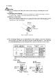
In addition to the above fittings and hose nipples, the below fittings can also be attached to the cylinder. When using the below fittings be sure to provide a speed controller after adjusting it to 500 mm/sec or less. 5) Piping connection to the cylinder Urethane tube Nylon tube Box nut Fitting body Gasket To cylinder port or elbow joint A hose nipple consists of two parts: a fitting body and a box nut. There are two sizes, one is for O.D.4mm / I.D.2.5mm tube and the other is for O.D.
I.D.4mm. This nipple fits both nylon tube and urethane tube. Connection process of nylon or urethane tube is as follows. 1) Remove the box nut, pass nylon tube or urethane tube through the nut. 2) Insert the tube into the fitting body. 3) Fasten the nut to the body. 6) When the cylinder direction is switched, select an appropriate solenoid valve for direction control from SMC stock. 3-Port solenoid valve is used for switching the valve. 2-4.
Compressed air that contains a large amount of drainage can cause the malfunction of pneumatic equipment, such as valves. Therefore, take appropriate measures to ensure air quality, such as by providing an aftercooler, air dryer, or water separator. 4) Ensure that the fluid and ambient temperatures are within the specified range. If the fluid temperature is 5°C or less, the moisture in the circuit could freeze, causing damage to the seals or equipment malfunction.
3.
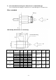
4. Dimensions 4-1. Dimensions Panel mounting type Exhaust port Exhaust port (Hose nipple) Mounting dimensions of CJ-5H-6. ( ) denotes the dimensions of CJ-5H-4.
4-2.
5. Troubleshooting Trouble Phenomenon Possible cause Remedy –The operation is not smooth. –The force output is reduced. –The cylinder doesn’t operate. Related section Air leakage (Piston seal leakage) A lack of pneumatic pressure The piston packing is worn due to grease washed away by water. 1) The pressure from the factory source is reduced. 2) The regulator setting has been displaced. 3) The piping is clogged. The lateral load has been exceeded. The speed is lower than specified piston speed.
Revision history 4-14-1, Sotokanda, Chiyoda-ku, Tokyo 101-0021 JAPAN Tel: + 81 3 5207 8249 Fax: +81 3 5298 5362 URL https://www.smcworld.com Note: Specifications are subject to change without prior notice and any obligation on the part of the manufacturer.