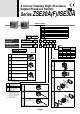
2-Colour Display High-Precision Digital Pressure Switch Settings can be copied to up to 10 slave sensors at once. The settings of the master sensor can be copied to the slave sensors. Reduced setting efforts Reduced chance of set-value input error Copy Master Slave → Unit 1 Unit 2 Unit 10 3-step setting 2 1 Push 3 Push Adjust to set-value with buttons. End setting Added vacuum range. 0 –101 kPa 1 MPa 0 –0.1 MPa Rated pressure range: 0.0 to –101.
Mounting Replaceable one-touch fittings Bracket configuration allows mounting in four positions. Bracket A Bracket B The clip type allows easy removal of fittings. Fitting’s type and size can be changed. Clip One-touch fitting Lead wire Connector cover added. Connector cover Mounting example Mounting example Lead wire with connector (2 m) Panel mount Mountable side by side without clearance 4-digit display 4-digit display allows easy reading of displayed values. Example: 0.
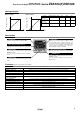
2-Colour Display High-Precision Digital Pressure Switch ® Series ZSE30A(F)/ISE30A How to Order Output Rated pressure range ISE30A –0.
Series ZSE30A(F)/ISE30A Specifications Model Rated pressure range Regulating pressure range Proof pressure Setting/display resolution Applicable fluid Power supply voltage Current consumption Switch output Maximum load current Maximum applied voltage Residual voltage Response time Short circuit protection Repeatability Hystere- Hysteresis mode sis Window comparator mode Note 2) Voltage output Analogue output Note 3) Current output ZSE30A (Vacuum pressure) ISE30A (Positive pressure) –100.0 to 100.
2-Colour Display High-Precision Digital Pressure Switch Series ZSE30A(F)/ISE30A Analogue Output Output current Analogue output [mA] Analogue output [V] Output voltage 5 1 0.6 AB C Pressure 20 Rated pressure range A B C 0.0 to –101.0 kPa — 0 –101 kPa For compound pressure –100.0 to 100.0 kPa — –100 kPa 100 kPa For positive pressure –0.100 to 1.000 MPa –0.1 kPa 0 1 MPa Range For vacuum pressure 4 2.
Series ZSE30A(F)/ISE30A Internal Circuits and Wiring Examples Z/ISE30A(F) Output N P NPN (1 output) PNP (1 output) Brown DC (+) Brown DC (+) + 12 to – 24 VDC Black OUT Main circuit Main circuit Load + Load FUNC FUNC Blue DC (–) Blue DC (–) Max. 28 V, 80 mA Residual voltage 1 V or less 12 to – 24 VDC Black OUT Max. 80 mA Residual voltage 1 V or less A B NPN (2 outputs) PNP (2 outputs) Brown DC (+) Brown DC (+) Load + White OUT2 FUNC Blue DC (–) Max.
2-Colour Display High-Precision Digital Pressure Switch C Series ZSE30A(F)/ISE30A E NPN (1 output) + Analogue voltage output PNP (1 output) + Analogue voltage output Brown DC (+) Brown DC (+) Black OUT1 White OUT2 Black OUT1 + – Main circuit Main circuit Load 12 to 24 VDC Load + White OUT2 Load FUNC FUNC – 12 to 24 VDC Load Blue DC (–) Blue DC (–) Max. 28 V, 80 mA Residual voltage 1 V or less Max. 80 mA Residual voltage 1 V or less Analogue voltage output Output impedance: Approx.
Series ZSE30A(F)/ISE30A Dimensions Z/ISE30A(F) Piping 01 / N01 20±0.1 25 2 x M3 x 0.5 thread depth 4 8 30 9.5 Lead wire with connector 10 30 20±0.1 M5 x 0.8 01: R1/8 N01: NPT1/8 1.5 C6H One-touch fitting ø4 mm ø5/32 inch straight N7H One-touch fitting ø6 mm straight 17.95 ø14 ø10 10.85 10.85 10.85 C4L C6L One-touch fitting ø4 mm ø5/32 inch elbow N7L One-touch fitting ø6 mm elbow 20.7 One-touch fitting ø1/4 inch elbow 23.45 16.1 15.6 22.85 ø9.3 10.85 ø10.3 21.75 ø14 ø9.
2-Colour Display High-Precision Digital Pressure Switch Series ZSE30A(F)/ISE30A With bracket Z/ISE30A(F) Option 2 A1 30 42.5 Bracket A (Option unit part no.: ZS-38-A1) 25 2 30 45 20 20 30 34.6 19 14.7 5.2 9.6 5.2 Note) Bracket configuration allows mounting in four directions. A2 42.5 (41.4) Bracket B (Option unit part no.: ZS-38-A2) Note) Bracket configuration allows mounting in four directions. 30 25 20 16.4 13.6 5.2 5.2 9.1 5.5 30 45 20 1.6 7.2 7.
Series ZSE30A(F)/ISE30A Dimensions Panel mount Z/ISE30A(F) Option 2 B Panel mount adapter (Option unit part no.: ZS-27-C) 7.2 47.8 17.8 9.5 8 .5 R4.5 21 R4 34.5 34.5 8.5 Panel thickness 0.5 to 6 D Panel mount adapter + Front protection cover (Option unit part no.: ZS-27-D) 42.4 11 17.8 8 9.5 33.5 33.5 Panel thickness 0.
2-Colour Display High-Precision Digital Pressure Switch Series ZSE30A(F)/ISE30A Panel fitting dimensions 1 pc. mounting Multiple (2 pcs. or more) horizontal mounting 0 31 –0.4 0 31 –0.4 0 31 –0.4 31 x n pcs. + 3.5 x (n pcs. – 1) x R2 R2 or or le s les ss Multiple (2 pcs. or more) vertical mounting 0 31 –0.4 24 or more 31 x n pcs. + 3.5 x (n pcs.
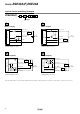
Series ZSE30A(F)/ISE30A Function Details A Copy function (F97) The settings of the master sensor can be copied to several slave sensors, which reduces the time taken for setting and prevents the input of wrong values. Settings can be copied to up to 10 slave sensors at once. (Max. transmission distance: 4 m) Unit 1 Unit 2 Master Unit 10 Steps to follow: 1) The sensors are connected by a dedicated lead wire (ZS-38-5L for master and one slave or ZS-38-U for master and up to 10 slaves).
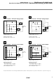
2-Colour Display High-Precision Digital Pressure Switch Series ZSE30A(F)/ISE30A F in brackets stand for the function codes. Refer to the operating manual for how to operate and function codes in detail. G Error indication function Error code Error description (LCD display) Solution Condition Shut off the power supply. After eliminating the output factor that caused the excess current, turn the power supply back on. Load current of switch output (OUT1) exceeds 80 mA.
Safety Instructions These safety instructions are intended to prevent hazardous situations and/or equipment damage. These instructions indicate the level of potential hazard with the labels of “Caution,” “Warning” or “Danger.” They are all important notes for safety and must be followed in addition to International Standards (ISO/IEC), Japan Industrial Standards (JIS) Note 1) and other safety regulations Note 2). Note 1) ISO 4414: Pneumatic fluid power – General rules relating to systems.
Safety Instructions Caution The product is provided for use in manufacturing industries. The product herein described is basically provided for peaceful use in manufacturing industries. If considering using the product in other industries, consult SMC beforehand and exchange specifications or a contract if necessary. If anything is unclear, contact your nearest sales branch.
Series ZSE30A(F)/ISE30A Specific Product Precautions 1 Be sure to read this before handling. Refer to the back of pages 1 and 2 for Safety Instructions and “Precautions for Handling Pneumatic Devices” (M-03-E3A) for Pressure Switches Precautions. Handling Warning Mounting Caution 1. Do not drop, bump, or apply excessive impacts (100 m/s2) while handling. Although the body of the pressure switch may not be damaged, the internal parts of the pressure switch could be damaged and lead to a malfunction. 2.
Series ZSE30A(F)/ISE30A Specific Product Precautions 2 Be sure to read before handling. Refer to the back of pages 1 and 2 for Safety Instructions and “Precautions for Handling Pneumatic Devices” (M-03-E3A) for Pressure Switches Precautions. Set Pressure Range and Rated Pressure Range Caution Set the pressure within the rated pressure range. The set pressure range is the range of pressure that is possible to be set.
EUROPEAN SUBSIDIARIES: Austria SMC Pneumatik GmbH (Austria). Girakstrasse 8, A-2100 Korneuburg Phone: +43 2262-62280, Fax: +43 2262-62285 E-mail: office@smc.at http://www.smc.at France SMC Pneumatique, S.A. 1, Boulevard de Strasbourg, Parc Gustave Eiffel Bussy Saint Georges F-77607 Marne La Vallee Cedex 3 Phone: +33 (0)1-6476 1000, Fax: +33 (0)1-6476 1010 E-mail: contact@smc-france.fr http://www.smc-france.