
Datasheet


1.
Do not drop, bump, or apply excessive impacts (980
m/s
2
) while handling. Although the body of the flow
monitor case may not be damaged, the inside of the flow
monitor could be damaged and lead to a malfunction.
2. The tensile strength of the power supply/output
connection cable is 50N and the sensor lead wire with a
connector is 25N. Applying a greater pulling force than
the applicable specified tensile strength to either of
these components can lead to a malfunction. When
handling, hold the body of the controller.
Wiring
Handling
Warning Caution
1. Incorrect wiring can damage the switch and cause a
malfunction or erroneous switch output. Connections
should be done while the power is turned off.
2. Do not attempt to insert or pull the flow rate sensor or
its connector when the power is on. Switch output may
malfunction.
3.
Wire separately from power lines and high voltage lines,
avoiding wiring in the same conduit with these lines.
Malfunctions may occur due to noise from these other lines.
4. If a commercial switching power supply is used, make
sure that the F.G. terminal is grounded.
Connection
Warning
1. Our 4-channel flow monitor is CE marked, however, it is
not equipped with surge protection against lightning.
Lightning surge countermeasures should be applied
directly to system components as necessary.
2. Our 4-channel flow monitor does not have an explosion
proof rating. Never use pressure sensors in the
presence of inflammable or explosive gases.
3. Enclosure "IP65" applies only to the front face of the
panel when mounting. Do not use in an environment
where oil splashing or spraying are anticipated.
Operating Environment
Warning
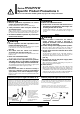
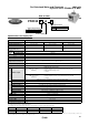
The front face of the panel mount conforms to IP65,
however there is a possibility of liquid infiltration if the
panel mount adapter is not installed securely and properly.
Securely fix the adapter with screws as shown below.
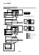
Mounting
Caution
4-channel Flow Monitor
Front protective
cover + Panel
mounting
Waterproof seal
(accessory)
Front protective cover
Panel
(ZS-26-B)
(accessory)
Panel mounting adapter
Mounting screw (M3 x 8 L)
42
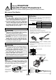
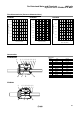
1.
Connecting sensor cable and connector (ZS-28-CA-)
• Cut the sensor cable as shown below.
• Insert each lead wire into the corresponding connector number
by following the chart provided below.
• Make sure that the numbers on the connector and the wire
colors match. After verifying that the wires are fully inserted,
temporarily hold A down by hand.
• Using pliers, press the center of A straight down.
• Note that that connector cannot be taken apart for reuse once it
is crimped. Use a new sensor connector if wiring or cable
insertion is done incorrectly.
2. Inserting/Detaching of sensor connector, power
supply/output connector
• Insert each connector straightforwardly until it clicks and locks
onto the body.
• To remove the connector, pull it straight out while pushing the
lever with your thumb.
Brown (DC+)
Not used
Blue (DC–)
White (IN: 1 to 5 V)
1
2
3
4
Cable wire colorConnector no.
Sensor connector port
Power supply/Output connector port
2 m
Pin no.
Lever
Lever
Sensor connector
Power supply/
Output connector
20 mm or more
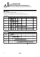
7 Green CH4_OUT1
8 Yellow N.C.
6 Red CH3_OUT1
5 Gray CH2_OUT1
4 White N.C.
3 Black CH1_OUT1
2 Blue DC (–)
1 Brown DC (+)
A
Specific Product Precautions 5
Be sure to read before handling. Refer to page 37 for safety instructions.
Series PF2A/PF2W
Tighten screws 1/4
to 1/2 turn after the
heads are flush with
the panel.