INSTALLATION GUIDE ta SMC6110L2 TigerSwitchTM 10/100 8-Port 10/100 Managed Switch plus 2 Gigabit Combo Ports
TigerSwitch 10/100 Installation Guide From SMC’s Tiger line of feature-rich workgroup LAN solutions 20 Mason Irvine, CA 92618 Phone: (949) 679-8000 January 2008 Pub.
Information furnished by SMC Networks, Inc. (SMC) is believed to be accurate and reliable. However, no responsibility is assumed by SMC for its use, nor for any infringements of patents or other rights of third parties which may result from its use. No license is granted by implication or otherwise under any patent or patent rights of SMC. SMC reserves the right to change specifications at any time without notice. Copyright © 2008 by SMC Networks, Inc. 20 Mason Irvine, CA 92618 All rights reserved.
Compliances and Safety Warnings FCC - Class A This equipment has been tested and found to comply with the limits for a Class A digital device, pursuant to part 15 of the FCC Rules. These limits are designed to provide reasonable protection against harmful interference when the equipment is operated in a commercial environment.
CE Mark Declaration of Conformance for EMI and Safety (EEC) This information technology equipment complies with the requirements of the Council Directive 89/336/EEC on the Approximation of the laws of the Member States relating to Electromagnetic Compatibility and 73/23/EEC for electrical equipment used within certain voltage limits and the Amendment Directive 93/68/EEC.
Safety Compliance Warning: Fiber Optic Port Safety CLASS I LASER DEVICE When using a fiber optic port, never look at the transmit laser while it is powered on. Also, never look directly at the fiber TX port and fiber cable ends when they are powered on. Avertissment: Ports pour fibres optiques - sécurité sur le plan optique DISPOSITIF LASER DE CLASSE I Ne regardez jamais le laser tant qu'il est sous tension.
Important! Before making connections, make sure you have the correct cord set. Check it (read the label on the cable) against the following: Power Cord Set U.S.A. and Canada The cord set must be UL-approved and CSA certified. The minimum specifications for the flexible cord are: - No. 18 AWG - not longer than 2 meters, or 16 AWG.
France et Pérou uniquement: Ce groupe ne peut pas être alimenté par un dispositif à impédance à la terre. Si vos alimentations sont du type impédance à la terre, ce groupe doit être alimenté par une tension de 230 V (2 P+T) par le biais d’un transformateur d’isolement à rapport 1:1, avec un point secondaire de connexion portant l’appellation Neutre et avec raccordement direct à la terre (masse).
Stromkabel. Dies muss von dem Land, in dem es benutzt wird geprüft werden: Schweiz Dieser Stromstecker muß die SEV/ASE 1011Bestimmungen einhalten. Europe Das Netzkabel muß vom Typ HO3VVF3GO.75 (Mindestanforderung) sein und die Aufschrift oder tragen. Der Netzstecker muß die Norm CEE 7/7 erfüllen (”SCHUKO”). Warnings and Cautionary Messages Warning: This product does not contain any serviceable user parts.
Environmental Statement The manufacturer of this product endeavours to sustain an environmentally-friendly policy throughout the entire production process. This is achieved though the following means: • Adherence to national legislation and regulations on environmental production standards. • Conservation of operational resources. • Waste reduction and safe disposal of all harmful un-recyclable by-products. • Recycling of all reusable waste content.
viii
About This Guide Purpose This guide details the hardware features of the switch, including the physical and performance-related characteristics, and how to install the switch. Audience The guide is intended for use by network administrators who are responsible for installing and setting up network equipment; consequently, it assumes a basic working knowledge of LANs (Local Area Networks).
x
Contents Chapter 1: Introduction Overview Switch Architecture Network Management Options Description of Hardware 10BASE-T/100BASE-TX Ports 1000BASE-T/SFP Ports Port and System Status LEDs Power Supply Socket Features and Benefits Connectivity Expandability Performance Management Chapter 2: Network Planning 1-1 1-1 1-2 1-2 1-2 1-2 1-3 1-3 1-4 1-4 1-4 1-5 1-5 1-5 2-1 Introduction to Switching Application Examples Collapsed Backbone Network Edge Deployment Application Notes 2-1 2-2 2-2 2-3 2-4 Chapter 3: I
Contents Chapter 4: Making Network Connections Connecting Network Devices Twisted-Pair Devices Cabling Guidelines Connecting to PCs, Servers, Hubs and Switches Network Wiring Connections Fiber Optic SFP Devices Connectivity Rules 1000BASE-T Cable Requirements 1000 Mbps Gigabit Ethernet Collision Domain 100 Mbps Fast Ethernet Collision Domain 10 Mbps Ethernet Collision Domain Cable Labeling and Connection Records 4-1 4-1 4-1 4-1 4-2 4-2 4-4 4-5 4-5 4-6 4-6 4-6 4-7 Appendix A: Troubleshooting A-1 Diagnosin
Tables Table 1-1 Table 1-2 Table 3-1 Table 4-1 Table 4-2 Table 4-3 Table 4-4 Table 4-5 Table 4-6 Table A-1 Table B-1 Table B-2 Port Status LEDs System Status LEDs Serial Cable Wiring Maximum 1000BASE-T Gigabit Ethernet Cable Length Maximum 1000BASE-SX Gigabit Ethernet Cable Lengths Maximum 1000BASE-LX Gigabit Ethernet Cable Length Maximum 1000BASE-LH Gigabit Ethernet Cable Length Maximum Fast Ethernet Cable Lengths Maximum Ethernet Cable Length Troubleshooting Chart 10/100BASE-TX MDI and MDI-X Port Pinouts
Figures Figure 1-1 Figure 1-2 Figure 1-3 Figure 2-1 Figure 2-2 Figure 3-1 Figure 3-2 Figure 3-3 Figure 3-4 Figure 3-5 Figure 3-6 Figure 3-7 Figure 4-1 Figure 4-2 Figure 4-3 Figure B-1 Figure B-2 Figure B-3 xiv Front and Rear Panels Port LEDs Power Supply Socket Collapsed Backbone Network Edge Deployment RJ-45 Connections Attaching the Brackets Installing the Switch in a Rack Attaching the Adhesive Feet Inserting an SFP Transceiver into a Slot Power Socket Serial Port (DB-9 DTE) Pin-Out Making Twisted-Pair
Chapter 1: Introduction Overview The SMC6110L2 is a Fast Ethernet switch with eight 10BASE-T/100BASE-TX ports and two 1000BASE-T ports that operate in combination with two Small Form Factor Pluggable (SFP) transceiver slots* (see Figure 1-1, Ports 9-10). The switch also includes an SNMP-based management agent, which provides both in-band and out-of-band access for managing the switch.
1 Introduction Switch Architecture The switch employs a wire-speed, non-blocking switching fabric. This permits simultaneous wire-speed transport of multiple packets at low latency on all ports. The switch also features full-duplex capability on all ports, which effectively doubles the bandwidth of each connection. This switch uses store-and-forward switching to ensure maximum data integrity.
1 Description of Hardware 1000BASE-T/SFP Ports These are combination Gigabit RJ-45 ports with shared Small Form Factor Pluggable (SFP) transceiver slots. If an SFP transceiver (purchased separately) is installed in a slot and has a valid link on the port, the associated RJ-45 port is disabled. The 1000BASE-T RJ-45 ports support automatic MDI/MDI-X operation, so you can use straight-through cables for all network connections to PCs or servers, or to other switches or hubs.
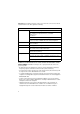
1 Introduction Table 1-2 System Status LEDs LED Condition PWR On Green The unit’s internal power supply is operating normally. Off The unit has no power connected. On Green The system diagnostic test has completed successfully. Flashing Green The system diagnostic test is in progress. On Amber The system diagnostic test has detected a fault. Diag Status Power Supply Socket There is one power socket on the rear panel of the switch. The standard power socket is for the AC power cord.
Features and Benefits 1 Expandability • Two Small Form Factor Pluggable (SFP) transceiver slots (shared with 1000BASE-T ports) • Supports 1000BASE-SX, 1000BASE-LX and 1000BASE-LH SFP transceivers. Performance • • • • • • Transparent bridging Aggregate duplex bandwidth of up to 5.6 Gbps Switching table with a total of 8K MAC address entries Provides store-and-forward switching Wire-speed filtering and forwarding Supports flow control, using back pressure for half duplex and IEEE 802.
1 1-6 Introduction
Chapter 2: Network Planning Introduction to Switching A network switch allows simultaneous transmission of multiple packets via non-crossbar switching. This means that it can partition a network more efficiently than bridges or routers. The switch has, therefore, been recognized as one of the most important building blocks for today’s networking technology.
2 Network Planning Application Examples The switch is not only designed to segment your network, but also to provide a wide range of options in setting up network connections. Some typical applications are described below. Collapsed Backbone The switch is an excellent choice for mixed Ethernet, Fast Ethernet, and Gigabit Ethernet installations where significant growth is expected in the near future.
Application Examples 2 Network Edge Deployment With 8 1000 Mbps parallel bridging ports (i.e., 8 distinct collision domains), this switch can function as an efficient bridged node that is ideal for a meeting room environment. Zero noise makes the switch inobtrusive for such a setting. In the figure below, the SMC6110L2 is connected to a central wiring closet via a 1000BASE-SX connection. The 1000BASE-T RJ-45 ports on the switch are providing 10/100 Mbps full-duplex connections for PCs and notebooks.
2 Network Planning Application Notes 1. Full-duplex operation only applies to point-to-point access (such as when a switch is attached to a workstation, server or another switch). When the switch is connected to a hub, both devices must operate in half-duplex mode. 2. Avoid using flow control on a port connected to a hub unless it is actually required to solve a problem. Otherwise back pressure jamming signals may degrade overall performance for the segment attached to the hub. 3.
Chapter 3: Installing the Switch Selecting a Site Switch units can be mounted in a standard 19-inch equipment rack or on a flat surface. Be sure to follow the guidelines below when choosing a location. • The site should: - be at the center of all the devices you want to link and near a power outlet.
3 Installing the Switch RJ-45 Connector Figure 3-1 RJ-45 Connections Equipment Checklist After unpacking this switch, check the contents to be sure you have received all the components. Then, before beginning the installation, be sure you have all other necessary installation equipment.
Mounting 3 Mounting The switch can be mounted in a standard 19-inch equipment rack or on a desktop or shelf. Mounting instructions for each type of site follow. Rack Mounting Before rack mounting the switch, pay particular attention to the following factors: • Temperature: Since the temperature within a rack assembly may be higher than the ambient room temperature, check that the rack-environment temperature is within the specified operating temperature range. (See page C-1.
3 2. Installing the Switch Mount the device in the rack, using four rack-mounting screws (not provided). Be sure to secure the lower rack-mounting screws first to prevent the brackets being bent by the weight of the switch. Figure 3-3 Installing the Switch in a Rack 3. If installing a single switch only, turn to “Connecting to a Power Source” at the end of this chapter. 4. If installing multiple switches, mount them in the rack, one below the other, in any order.
3 Installing an Optional SFP Transceiver Desktop or Shelf Mounting 1. Attach the four adhesive feet to the bottom of the first switch. Figure 3-4 Attaching the Adhesive Feet 2. Set the device on a flat surface near an AC power source, making sure there are at least two inches of space on all sides for proper air flow. 3. If installing a single switch only, go to “Connecting to a Power Source” at the end of this chapter. 4. If installing multiple switches, attach four adhesive feet to each one.
3 Installing the Switch The SFP slots support the following optional SFP transceivers: • 1000BASE-SX • 1000BASE-LX • 1000BASE-LH To install an SFP transceiver, do the following: 1. Consider network and cabling requirements to select an appropriate SFP transceiver type. 2. Insert the transceiver with the optical connector facing outward and the slot connector facing down. Note that SFP transceivers are keyed so they can only be installed in one orientation. 3.
Connecting to the Console Port 3 Connecting to the Console Port The DB-9 serial port on the switch’s back panel is used to connect to the switch for out-of-band console configuration. The command-line-driven configuration program can be accessed from a terminal or a PC running a terminal emulation program. The pin assignments used to connect to the serial port are provided in the following table.
3 3-8 Installing the Switch
Chapter 4: Making Network Connections Connecting Network Devices The switch is designed to be connected to 10 or 100 Mbps network cards in PCs and servers, as well as to other switches and hubs. It may also be connected to remote devices using optional 1000BASE-SX, 1000BASE-LX, or 1000BASE-LH SFP transceivers. Twisted-Pair Devices Each device requires an unshielded twisted-pair (UTP) cable with RJ-45 connectors at both ends.
4 Making Network Connections Connecting to PCs, Servers, Hubs and Switches 1. Attach one end of a twisted-pair cable segment to the device’s RJ-45 connector. Figure 4-1 Making Twisted-Pair Connections 2. If the device is a network card and the switch is in the wiring closet, attach the other end of the cable segment to a modular wall outlet that is connected to the wiring closet. (See the section “Network Wiring Connections.”) Otherwise, attach the other end to an available port on the switch.
Twisted-Pair Devices 3. 4 Label the cables to simplify future troubleshooting. See “Cable Labeling and Connection Records” on page 4-7.
4 Making Network Connections Fiber Optic SFP Devices An optional Gigabit SFP transceiver (1000BASE-SX, 1000BASE-LX or 1000BASE-LH) can be used for a backbone connection between switches, or for connecting to a high-speed server. Each single-mode fiber port requires 9/125 micron single-mode fiber optic cable with an LC connector at both ends. Each multimode fiber optic port requires 50/125 or 62.5/125 micron multimode fiber optic cabling with an LC connector at both ends.
4 Connectivity Rules 46 Figure 4-3 Making Fiber Port Connections 4. As a connection is made, check the Link LED on the switch corresponding to the port to be sure that the connection is valid. The 1000BASE-SX, 1000BASE-LX, 1000BASE-LH fiber optic ports operate at 1 Gbps, full duplex, with auto-negotiation of flow control. The maximum length for fiber optic cable operating at Gigabit speed will depend on the fiber type as listed under “1000 Mbps Gigabit Ethernet Collision Domain” on page 4-6.
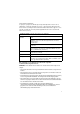
4 Making Network Connections 1000 Mbps Gigabit Ethernet Collision Domain Table 4-1 Maximum 1000BASE-T Gigabit Ethernet Cable Length Cable Type Maximum Cable Length Category 5, 5e, or 6 100-ohm UTP or STP 100 m (328 ft) Connector RJ-45 Table 4-2 Maximum 1000BASE-SX Gigabit Ethernet Cable Lengths Fiber Size Fiber Bandwidth Maximum Cable Length Connector 62.
Cable Labeling and Connection Records 4 Cable Labeling and Connection Records When planning a network installation, it is essential to label the opposing ends of cables and to record where each cable is connected. Doing so will enable you to easily locate inter-connected devices, isolate faults and change your topology without need for unnecessary time consumption. To best manage the physical implementations of your network, follow these guidelines: • Clearly label the opposing ends of each cable.
4 4-8 Making Network Connections
Appendix A: Troubleshooting Diagnosing Switch Indicators Table A-1 Troubleshooting Chart Symptom Action Power LED is Off • Check connections between the switch, the power cord and the wall outlet. • Contact your dealer for assistance. Diag LED is Amber • Power cycle the switch to try and clear the condition. • If the condition does not clear, contact your dealer for assistance. Link LED is Off • Verify that the switch and attached device are powered on.
A Troubleshooting In-Band Access You can access the management agent in the switch from anywhere within the attached network using Telnet, a web browser, or other network management software tools. However, you must first configure the switch with a valid IP address, subnet mask, and default gateway. If you have trouble establishing a link to the management agent, check to see if you have a valid network connection. Then verify that you entered the correct IP address.
Appendix B: Cables Twisted-Pair Cable and Pin Assignments For 10/100BASE-TX connections, the twisted-pair cable must have two pairs of wires. For 1000BASE-T connections the twisted-pair cable must have four pairs of wires. Each wire pair is identified by two different colors. For example, one wire might be green and the other, green with white stripes. Also, an RJ-45 connector must be attached to both ends of the cable. Caution: DO NOT plug a phone jack connector into any RJ-45 port.
B Cables Table B-1 10/100BASE-TX MDI and MDI-X Port Pinouts Pin MDI Signal Name MDI-X Signal Name 1 Transmit Data plus (TD+) Receive Data plus (RD+) 2 Transmit Data minus (TD-) Receive Data minus (RD-) 3 Receive Data plus (RD+) Transmit Data plus (TD+) 6 Receive Data minus (RD-) Transmit Data minus (TD-) 4,5,7,8 Not used Not used Note: The “+” and “-” signs represent the polarity of the wires that make up each wire pair.
Twisted-Pair Cable and Pin Assignments B Crossover Wiring If the twisted-pair cable is to join two ports and either both ports are labeled with an “X” (MDI-X) or neither port is labeled with an “X” (MDI), a crossover must be implemented in the wiring. (When auto-negotiation is enabled for any RJ-45 port on this switch, you can use either straight-through or crossover cable to connect to any device type.) You must connect all four wire pairs as shown in the following diagram to support Gigabit Ethernet.
B Cables Table B-2 1000BASE-T MDI and MDI-X Port Pinouts Pin MDI Signal Name MDI-X Signal Name 5 Bi-directional Data Three Minus (BI_D3-) Bi-directional Data Four Minus (BI_D4-) 6 Bi-directional Data Two Minus (BI_D2-) Bi-directional Data One Minus (BI_D1-) 7 Bi-directional Data Four Plus (BI_D4+) Bi-directional Data Three Plus (BI_D3+) 8 Bi-directional Data Four Minus (BI_D4-) Bi-directional Data Three Minus (BI_D3-) Cable Testing for Existing Category 5 Cable Installed Category 5 cabling m
Appendix C: Specifications Physical Characteristics Ports 8 10/100BASE-TX, with auto-negotiation 2 10/100/1000BASE-T shared with two SFP transceiver slots Network Interface Ports 1-10: RJ-45 connector, auto MDI/X 10BASE-T: RJ-45 (100-ohm, UTP cable; Category 3 or better) 100BASE-TX: RJ-45 (100-ohm, UTP cable; Category 5 or better) 1000BASE-T: RJ-45 (100-ohm, UTP or STP cable; Category 5, 5e or 6) *Maximum Cable Length - 100 m (328 ft) Buffer Architecture 2 Mbits Aggregate Bandwidth 5.
C Specifications AC Input 100 to 240 V, 50-60 Hz, 0.4A Power Supply Internal, auto-ranging transformer: 100 to 240 VAC, 50 to 60 Hz Power Consumption 13.2 Watts maximum Maximum Current 0.4 A @ 100 VAC 0.2 A @ 240 VAC Switch Features Forwarding Mode Store-and-forward Throughput Wire speed Flow Control Full Duplex: IEEE 802.
Standards C Standards IEEE 802.3-2005 Ethernet, Fast Ethernet, Gigabit Ethernet Full-duplex flow control Link Aggregation Control Protocol IEEE 802.1D Spanning Tree Protocol IEEE 802.
C C-4 Specifications
Appendix D: Ordering Information Table D-1 TIgerSwitch 10/100 Products and Accessories Product Number Description SMC6110L2 8-port 10/100 Managed Switch with 2 Gigabit Combo ports SMC1GSFP-SX Single-port 1000BASE-SX Small Form Pluggable (SFP) mini-GBIC transceiver SMC1GSFP-LX Single-port 1000BASE-LX Small Form Pluggable (SFP) mini-GBIC transceiver SMC1GSFP-ZX Single-port 1000BASE-ZX Small Form Pluggable (SFP) mini-GBIC transceiver D-1
D D-2 Ordering Information
Glossary 10BASE-T IEEE 802.3 specification for 10 Mbps Ethernet over two pairs of Category 3, 4, or 5 UTP cable. 100BASE-FX IEEE 802.3 specification for 100 Mbps Ethernet over two strands of 50/125, 62.5/ 125 micron, or 9/125 micron core fiber cable. 100BASE-TX IEEE 802.3u specification for 100 Mbps Ethernet over two pairs of Category 5 UTP cable. 1000BASE-LX IEEE 802.3z specification for Gigabit Ethernet over two strands of 50/125, 62.5/125 or 9/125 micron core fiber cable.
Glossary Collision A condition in which packets transmitted over the cable interfere with each other. Their interference makes both signals unintelligible. Collision Domain Single CSMA/CD LAN segment. CSMA/CD CSMA/CD (Carrier Sense Multiple Access/Collision Detect) is the communication method employed by Ethernet, Fast Ethernet, and Gigabit Ethernet. End Station A workstation, server, or other device that does not forward traffic.
Glossary IEEE 802.3u Defines CSMA/CD access method and physical layer specifications for 100BASE-TX Fast Ethernet. (Now incorporated in IEEE 802.3-2002.) IEEE 802.3x Defines Ethernet frame start/stop requests and timers used for flow control on full-duplex links. (Now incorporated in IEEE 802.3-2002.) IEEE 802.3z Defines CSMA/CD access method and physical layer specifications for 1000BASE Gigabit Ethernet. (Now incorporated in IEEE 802.3-2002.) LAN Segment Separate LAN or collision domain.
Glossary RJ-45 Connector A connector for twisted-pair wiring. Switched Ports Ports that are on separate collision domains or LAN segments. TIA Telecommunications Industry Association Transmission Control Protocol/Internet Protocol (TCP/IP) Protocol suite that includes TCP as the primary transport protocol, and IP as the network layer protocol. UTP Unshielded twisted-pair cable.
Index Numerics 10 Mbps connectivity rules 4-6 100 Mbps connectivity rules 4-6 1000 Mbps connectivity rules 4-6 1000BASE-LH fiber cable Lengths 4-6 1000BASE-LX fiber cable Lengths 4-6 1000BASE-SX fiber cable Lengths 4-6 1000BASE-T pin assignments B-3 ports 1-3 100BASE-TX cable lengths 4-6 ports 1-2 10BASE-T cable lengths 4-6 ports 1-2 A adhesive feet, attaching 3-5 air flow requirements 3-1 applications central wiring closet 2-3 collapsed backbone 2-2 remote connections with fiber 2-4 VLAN connections 2-5
Index site requirements 3-1 R L laser safety 4-4 LC port connections 4-4 LED indicators Diag 1-4 Power 1-4 problems A-1 location requirements 3-1 M management agent 1-2 features 1-5, C-2 out-of-band 1-2 SNMP 1-2 web-based 1-2 modules 100BASE-FX C-3 mounting the switch in a rack 3-3 on a desktop or shelf 3-5 multimode fiber optic cables 4-4 N network connections 4-1, 4-4 examples 2-2 O out-of-band management 1-2 rack mounting 3-3 rear panel of switch 1-1 rear panel receptacles 1-4 RJ-45 port 1-2, 1-3 co
Index V W VLANS tagging 2-5 web-based management 1-2 Index-3
Index Index-4
TECHNICAL SUPPORT From U.S.A. and Canada (24 hours a day, 7 days a week) Phn: 800-SMC-4-YOU / 949-679-8000 Fax: 949-502-3400 ENGLISH Technical Support information available at www.smc.com FRENCH Informations Support Technique sur www.smc.com DEUTSCH Technischer Support und weitere Information unter www.smc.com SPANISH En www.smc.com Ud. podrá encontrar la información relativa a servicios de soporte técnico DUTCH Technische ondersteuningsinformatie beschikbaar op www.smc.