TigerSwitch 10/100 24-Port 10/100 Mbps Fast Ethernet Managed Switch ◆ ◆ ◆ ◆ ◆ ◆ ◆ ◆ ◆ ◆ 24 auto-MDI/MDI-X 10/100BASE-TX ports 4 Gigabit RJ-45/SFP combination ports Non-blocking switching architecture Spanning Tree Protocol, and Rapid STP Up to 8 LACP or static trunks CoS support through four priority queues Full support for VLANs with GVRP IGMP multicast filtering and snooping Support for jumbo frames up to 9 KB Manageable via console, Web, SNMP, RMON Installation Guide Installationsanleitung SMC6128L2
TigerSwitch 10/100 Installation Guide From SMC’s Tiger line of feature-rich workgroup LAN solutions 20 Mason Irvine, CA 92618 Phone: (949) 679-8000 March 2007 Pub.
Information furnished by SMC Networks, Inc. (SMC) is believed to be accurate and reliable. However, no responsibility is assumed by SMC for its use, nor for any infringements of patents or other rights of third parties which may result from its use. No license is granted by implication or otherwise under any patent or patent rights of SMC. SMC reserves the right to change specifications at any time without notice. Copyright © 2007 by SMC Networks, Inc. 20 Mason Irvine, CA 92618 All rights reserved.
LIMITED WARRANTY Limited Warranty Statement: SMC Networks, Inc. (“SMC”) warrants its products to be free from defects in workmanship and materials, under normal use and service, for the applicable warranty term. All SMC products carry a standard 90-day limited warranty from the date of purchase from SMC or its Authorized Reseller. SMC may, at its own discretion, repair or replace any product not operating as warranted with a similar or functionally equivalent product, during the applicable warranty term.
LIMITED WARRANTY WARRANTIES EXCLUSIVE: IF AN SMC PRODUCT DOES NOT OPERATE AS WARRANTED ABOVE, CUSTOMER’S SOLE REMEDY SHALL BE REPAIR OR REPLACEMENT OF THE PRODUCT IN QUESTION, AT SMC’S OPTION. THE FOREGOING WARRANTIES AND REMEDIES ARE EXCLUSIVE AND ARE IN LIEU OF ALL OTHER WARRANTIES OR CONDITIONS, EXPRESS OR IMPLIED, EITHER IN FACT OR BY OPERATION OF LAW, STATUTORY OR OTHERWISE, INCLUDING WARRANTIES OR CONDITIONS OF MERCHANTABILITY AND FITNESS FOR A PARTICULAR PURPOSE.
COMPLIANCES FCC - Class A This equipment has been tested and found to comply with the limits for a Class A digital device, pursuant to part 15 of the FCC Rules. These limits are designed to provide reasonable protection against harmful interference when the equipment is operated in a commercial environment. This equipment generates, uses, and can radiate radio frequency energy and, if not installed and used in accordance with the instruction manual, may cause harmful interference to radio communications.
COMPLIANCES CE Mark Declaration of Conformance for EMI and Safety (EEC) SMC contact for these products in Europe is: SMC Networks Europe, Edificio Conata II, Calle Fructuós Gelabert 6-8, 2o, 4a, 08970 - Sant Joan Despí, Barcelona, Spain.
COMPLIANCES Safety Compliance Warning: Fiber Optic Port Safety CLASS I LASER DEVICE When using a fiber optic port, never look at the transmit laser while it is powered on. Also, never look directly at the fiber TX port and fiber cable ends when they are powered on. Avertissment: Ports pour fibres optiques - sécurité sur le plan optique DISPOSITIF LASER DE CLASSE I Ne regardez jamais le laser tant qu’il est sous tension.
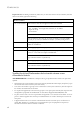
COMPLIANCES Important! Before making connections, make sure you have the correct cord set. Check it (read the label on the cable) against the following: Power Cord Set U.S.A. and Canada The cord set must be UL-approved and CSA certified. The minimum specifications for the flexible cord are: - No. 18 AWG - not longer than 2 meters, or 16 AWG.
COMPLIANCES France et Pérou uniquement: Ce groupe ne peut pas être alimenté par un dispositif à impédance à la terre. Si vos alimentations sont du type impédance à la terre, ce groupe doit être alimenté par une tension de 230 V (2 P+T) par le biais d’un transformateur d’isolement à rapport 1:1, avec un point secondaire de connexion portant l’appellation Neutre et avec raccordement direct à la terre (masse).
COMPLIANCES Stromkabel. Dies muss von dem Land, in dem es benutzt wird geprüft werden: Schweiz Dieser Stromstecker muß die SEV/ASE 1011Bestimmungen einhalten. Europe Das Netzkabel muß vom Typ HO3VVF3GO.75 (Mindestanforderung) sein und die Aufschrift oder tragen. Der Netzstecker muß die Norm CEE 7/7 erfüllen (”SCHUKO”). Warnings and Cautionary Messages Warning: This product does not contain any serviceable user parts.
COMPLIANCES Environmental Statement The manufacturer of this product endeavours to sustain an environmentally-friendly policy throughout the entire production process. This is achieved though the following means: • • • • • • Adherence to national legislation and regulations on environmental production standards. Conservation of operational resources. Waste reduction and safe disposal of all harmful un-recyclable by-products. Recycling of all reusable waste content.
COMPLIANCES x
TABLE OF CONTENTS 1 About the TigerSwitch . . . . . . . . . . . . . . . . . . . . . . . . .1-1 Overview . . . . . . . . . . . . . . . . . . . . . . . . . . . . . . . . . . . . . . . . . . . . . . . . . . 1-1 Switch Architecture . . . . . . . . . . . . . . . . . . . . . . . . . . . . . . . . . . . 1-2 Network Management Options . . . . . . . . . . . . . . . . . . . . . . . . . . 1-2 Description of Hardware . . . . . . . . . . . . . . . . . . . . . . . . . . . . . . . . . . . . . 1-2 10/100BASE-T Ports . . .
TABLE OF CONTENTS Connecting to a Power Source . . . . . . . . . . . . . . . . . . . . . . . . . . . . . . . . 3-8 Connecting to the Console Port . . . . . . . . . . . . . . . . . . . . . . . . . . . . . . . 3-9 Wiring Map for Serial Cable . . . . . . . . . . . . . . . . . . . . . . . . . . . . . 3-9 4 Making Network Connections . . . . . . . . . . . . . . . . . . . 4-1 Connecting Network Devices . . . . . . . . . . . . . . . . . . . . . . . . . . . . . . . . . Twisted-Pair Devices . . . . . . . . . . . .
TABLE OF CONTENTS Standards . . . . . . . . . . . . . . . . . . . . . . . . . . . . . . . . . . . . . . . . . . . . . . . . . . C-3 Compliances . . . . . . . . . . . . . . . . . . . . . . . . . . . . . . . . . . . . . . . . . . . . . . . C-3 D Ordering Information . . . . . . . . . . . . . . . . . . . . . . . . . D-1 E German Instructions . . . . . . . . . . . . . . . . . . . . . . . . . . E-1 Eine Site Auswählen (Selecting a Site) . . . . . . . . . . . . . . . . . . . . . . . . . .
TABLE OF CONTENTS xiv
TABLES Table 1-1 Table 1-2 Table 3-1 Table 4-1 Table 4-3 Table 4-4 Table 4-5 Table 4-2 Table 4-6 Table A-1 Table B-1 Table B-2 Table D-1 Port Status LEDs . . . . . . . . . . . . . . . . . . . . . . . . . . . . . . . . . 1-4 System Status LEDs . . . . . . . . . . . . . . . . . . . . . . . . . . . . . . . 1-5 Serial Cable Wiring . . . . . . . . . . . . . . . . . . . . . . . . . . . . . . . . 3-9 Maximum 1000BASE-T Gigabit Ethernet Cable Length . .
xvi
FIGURES Figure 1-1 Figure 1-2 Figure 1-3 Figure 1-4 Figure 2-1 Figure 2-2 Figure 2-3 Figure 2-4 Figure 3-1 Figure 3-2 Figure 3-3 Figure 3-4 Figure 3-5 Figure 3-6 Figure 3-7 Figure 4-1 Figure 4-2 Figure 4-3 Figure B-1 Figure B-2 Figure B-3 Front and Rear Panels . . . . . . . . . . . . . . . . . . . . . . . . . . . . 1-1 Port LEDs . . . . . . . . . . . . . . . . . . . . . . . . . . . . . . . . . . . . . 1-3 System LEDs . . . . . . . . . . . . . . . . . . . . . . . . . . . . . . . . . . .
FIGURES xviii
CHAPTER 1 ABOUT THE TIGERSWITCH Overview The SMC6128L2 is a Fast Ethernet switch with 24 10/100BASE-TX ports and four Gigabit combination ports1 that are comprised of an RJ-45 port and an SFP transceiver slot. The switch also includes an SNMP-based management agent embedded on the main board. This agent supports both in-band and out-of-band access for managing the switch.
ABOUT THE TIGERSWITCH Switch Architecture The SMC6128L2 switch employs a wire-speed, non-blocking switching fabric. This permits simultaneous wire-speed transport of multiple packets at low latency on all ports. The switch also features full-duplex capability on all ports, which effectively doubles the bandwidth of each connection. This switch uses store-and-forward switching to ensure maximum data integrity.
DESCRIPTION OF HARDWARE Each of these ports support auto-negotiation, so the optimum transmission mode (half or full duplex), and data rate (10 or 100 Mbps) can be selected automatically. If a device connected to one of these ports does not support auto-negotiation, the communication mode of that port can be configured manually. Each port also supports auto-negotiation of flow control, so the switch can automatically prevent port buffers from becoming saturated.
ABOUT THE TIGERSWITCH Table 1-1 LED Port Status LEDs Condition Status On/Blinking Green The port has established a valid 100 Mbps link. Blinking indicates activity. On/Blinking Amber The port has established a valid 10 Mbps link. Blinking indicates activity. Off There is no valid link on the port. RJ-45 Ports Link/ACT (Link/ Activity) Combination Gigabit Ports Link/ACT (Link/ Activity) On/Blinking Green The port has established a valid link. Blinking indicates activity.
DESCRIPTION OF HARDWARE Table 1-2 System Status LEDs LED Condition Status PWR (Power) On Green The unit’s internal power supply is operating normally. On Amber The unit’s internal power supply has failed. Off The unit has no power connected or has failed. On Green The system diagnostic test has completed successfully. Blinking Green The system diagnostic test is in progress. On Amber The system diagnostic test has detected a fault.
ABOUT THE TIGERSWITCH Features and Benefits Connectivity • 24 10/100BASE-TX ports plus four Gigabit combination ports (RJ-45/SFP). • Auto-negotiation enables each RJ-45 port to automatically select the optimum speed (10 or 100 Mbps), and the communication mode (half or full duplex) if this feature is supported by the attached device; otherwise the port can be configured manually. • Independent RJ-45 10/100BASE-TX ports with auto MDI/MDI-X pinout selection.
FEATURES AND BENEFITS • Supports wire-speed filtering and forwarding • Supports flow control, using back pressure for half duplex and IEEE 802.
ABOUT THE TIGERSWITCH 1-8
CHAPTER 2 NETWORK PLANNING Introduction to Switching A network switch allows simultaneous transmission of multiple packets via non-crossbar switching. This means that it can partition a network more efficiently than bridges or routers. The switch has, therefore, been recognized as one of the most important building blocks for today’s networking technology.
NETWORK PLANNING Application Examples The SMC6128L2 switch is not only designed to segment your network, but also to provide a wide range of options in setting up network connections. Some typical applications are described below. Collapsed Backbone The SMC6128L2 switch is an excellent choice for Ethernet, Fast Ethernet, and Gigabit Ethernet installations where significant growth is expected in the near future.
APPLICATION EXAMPLES Network Aggregation Plan With 28 parallel bridging ports (i.e., 28 distinct collision domains), the SMC6128L2 switch can collapse a complex network down into a single efficient bridged node, increasing overall bandwidth and throughput. In the figure below, the 10/100BASE-TX ports are providing 100 Mbps connectivity through layer 2 switches. In addition, the switch is also connecting several servers at 1000 Mbps. Server Farm 10/100 Mbps Segments ... ...
NETWORK PLANNING Remote Connections with Fiber Cable Fiber optic technology allows for longer cabling than any other media type. A 1000BASE-SX (MMF) link can connect to a site up to 550 meters away, a 1000BASE-LX (SMF) link up to 5 km, and a 1000BASE-ZX link up to 100 km. This allows the Switch to serve as a collapsed backbone, providing direct connectivity for a widespread LAN.
APPLICATION EXAMPLES Making VLAN Connections This switch supports VLANs which can be used to organize any group of network nodes into separate broadcast domains. VLANs confine broadcast traffic to the originating group, and can eliminate broadcast storms in large networks. This provides a more secure and cleaner network environment. VLANs can be based on untagged port groups, or traffic can be explicitly tagged to identify the VLAN group to which it belongs.
NETWORK PLANNING Application Notes 1. Full-duplex operation only applies to point-to-point access (such as when a switch is attached to a workstation, server or another switch). When the switch is connected to a hub, both devices must operate in half-duplex mode. 2. Avoid using flow control on a port connected to a hub unless it is actually required to solve a problem. Otherwise back pressure jamming signals may degrade overall performance for the segment attached to the hub. 3.
CHAPTER 3 INSTALLING THE SWITCH Selecting a Site Switch units can be mounted in a standard 19-inch equipment rack or on a flat surface. Be sure to follow the guidelines below when choosing a location. • The site should: - be at the center of all the devices you want to link and near a power outlet.
INSTALLING THE SWITCH Ethernet Cabling To ensure proper operation when installing the switch into a network, make sure that the current cables are suitable for 10BASE-T, 100BASE-TX or 1000BASE-T operation. Check the following criteria against the current installation of your network: • Cable type: Unshielded twisted pair (UTP) or shielded twisted pair (STP) cables with RJ-45 connectors; Category 3 or better for 10BASE-T, Category 5 or better for 100BASE-TX, and Category 5, 5e or 6 for 1000BASE-T.
EQUIPMENT CHECKLIST Equipment Checklist After unpacking this switch, check the contents to be sure you have received all the components. Then, before beginning the installation, be sure you have all other necessary installation equipment.
INSTALLING THE SWITCH Mounting This switch can be mounted in a standard 19-inch equipment rack or on a desktop or shelf. Mounting instructions for each type of site follow. Rack Mounting Before rack mounting the switch, pay particular attention to the following factors: 3-4 • Temperature: Since the temperature within a rack assembly may be higher than the ambient room temperature, check that the rack-environment temperature is within the specified operating temperature range 0 °C to 40 °C.
MOUNTING To rack-mount devices: 1. Attach the brackets to the device using the screws provided in the Bracket Mounting Kit. Figure 3-2 Attaching the Brackets 2. Mount the device in the rack, using four rack-mounting screws (not provided).
INSTALLING THE SWITCH 3. If installing a single switch only, turn to “Connecting to a Power Source” at the end of this chapter. 4. If installing multiple switches, mount them in the rack, one below the other, in any order. Desktop or Shelf Mounting 1. Attach the four adhesive feet to the bottom of the first switch. Figure 3-4 Attaching the Adhesive Feet 2. Set the device on a flat surface near an AC power source, making sure there are at least two inches of space on all sides for proper air flow. 3.
INSTALLING AN OPTIONAL SFP TRANSCEIVER Installing an Optional SFP Transceiver Figure 3-5 Installing an SFP Transceiver into a Slot The SFP slots support the following optional SFP transceivers: • 1000BASE-SX • 1000BASE-LX • 1000BASE-ZX To install an SFP transceiver, do the following: 1. Consider network and cabling requirements to select an appropriate SFP transceiver type. 2. Insert the transceiver with the optical connector facing outward and the slot connector facing down.
INSTALLING THE SWITCH Connecting to a Power Source To connect a switch to a power source: 1. Insert the power cable plug directly into the power socket located at the back of the switch. Figure 3-6 Power Socket 2. Plug the other end of the cable into a grounded, 3-pin, AC power source. Note: For International use, you may need to change the AC line cord. You must use a line cord set that has been approved for the receptacle type in your country. 3.
CONNECTING TO THE CONSOLE PORT Connecting to the Console Port The DB-9 serial port on the switch’s rear panel is used to connect to the switch for out-of-band console configuration. The command-line-driven configuration program can be accessed from a terminal or a PC running a terminal emulation program. The pin assignments used to connect to the serial port are provided in the following table.
INSTALLING THE SWITCH 3-10
CHAPTER 4 MAKING NETWORK CONNECTIONS Connecting Network Devices The SMC6128L2 switch is designed to interconnect multiple segments (or collision domains). It can be connected to network cards in PCs and servers, as well as to hubs, switches or routers. It may also be connected to remote devices using the optional SFP transceivers. Twisted-Pair Devices Each device requires an unshielded twisted-pair (UTP) cable with RJ-45 connectors at both ends.
MAKING NETWORK CONNECTIONS Connecting to PCs, Servers, Hubs and Switches 1. Attach one end of a twisted-pair cable segment to the device’s RJ-45 connector. Figure 4-1 Making Twisted-Pair Connections 2. If the device is a network card and the switch is in the wiring closet, attach the other end of the cable segment to a modular wall outlet that is connected to the wiring closet. (See the section “Network Wiring Connections” on page 4-3) Otherwise, attach the other end to an available port on the switch.
TWISTED-PAIR DEVICES Network Wiring Connections Today, the punch-down block is an integral part of many of the newer equipment racks. It is actually part of the patch panel. Instructions for making connections in the wiring closet with this type of equipment follows. 1. Attach one end of a patch cable to an available port on the switch, and the other end to the patch panel. 2.
MAKING NETWORK CONNECTIONS Fiber Optic SFP Devices An optional Gigabit SFP transceiver (1000BASE-SX, 1000BASE-LX, or 1000BASE-ZX) can be used for a backbone connection between switches, or for connecting to a high-speed server. Each single-mode fiber port requires 9/125 micron single-mode fiber optic cable with an LC connector at both ends. Each multimode fiber optic port requires 50/125 or 62.5/125 micron multimode fiber optic cabling with an LC connector at both ends.
FIBER OPTIC SFP DEVICES 2. Check that the fiber terminators are clean. You can clean the cable plugs by wiping them gently with a clean tissue or cotton ball moistened with a little ethanol. Dirty fiber terminators on fiber optic cables will impair the quality of the light transmitted through the cable and lead to degraded performance on the port. 3. Connect one end of the cable to the LC port on the switch and the other end to the LC port on the other device.
MAKING NETWORK CONNECTIONS Connectivity Rules When adding hubs (repeaters) to your network, please follow the connectivity rules listed in the manuals for these products. However, note that because switches break up the path for connected devices into separate collision domains, you should not include the switch or connected cabling in your calculations for cascade length involving other devices.
CONNECTIVITY RULES Table 4-2 Maximum 1000BASE-SX Gigabit Ethernet Cable Lengths Fiber Size Fiber Bandwidth Maximum Cable Length Connector 62.
MAKING NETWORK CONNECTIONS 10 Mbps Ethernet Collision Domain Table 4-6 Maximum Ethernet Cable Length Cable Type Maximum Cable Length Connector Twisted Pair, Category 3 or better 100-ohm UTP 100 m (328 ft) RJ-45 Cable Labeling and Connection Records When planning a network installation, it is essential to label the opposing ends of cables and to record where each cable is connected.
APPENDIX A TROUBLESHOOTING Diagnosing Switch Indicators Table A-1 Troubleshooting Chart Symptom Action PWR LED is Off • Power supply is disconnected. • Check connections between the switch, the power cord and the wall outlet. • Contact your dealer for assistance. PWR LED is Amber • Internal power supply has failed. Contact your local dealer for assistance.
TROUBLESHOOTING Power Supply Problems If the power indicator does not turn on when the power cord is plugged in, you may have a problem with the power outlet, power cord, or internal power supply. However, if the unit powers off after running for a while, check for loose power connections, power losses or surges at the power outlet. If you still cannot isolate the problem, the internal power supply may be defective. Installation Verify that all system components have been properly installed.
APPENDIX B CABLES Twisted-Pair Cable and Pin Assignments For 10/100BASE-TX connections, the twisted-pair cable must have two pairs of wires. For 1000BASE-T connections the twisted-pair cable must have four pairs of wires. Each wire pair is identified by two different colors. For example, one wire might be green and the other, green with white stripes. Also, an RJ-45 connector must be attached to both ends of the cable.
CABLES 10BASE-T/100BASE-TX Pin Assignments Use unshielded twisted-pair (UTP) or shielded twisted-pair (STP) cable for RJ-45 connections: 100-ohm Category 3 or better cable for 10 Mbps connections, or 100-ohm Category 5 or better cable for 100 Mbps connections. Also be sure that the length of any twisted-pair connection does not exceed 100 meters (328 feet).
TWISTED-PAIR CABLE AND PIN ASSIGNMENTS Straight-Through Wiring If the twisted-pair cable is to join two ports and only one of the ports has an internal crossover (MDI-X), the two pairs of wires must be straight-through. (When auto-negotiation is enabled for any RJ-45 port on this switch, you can use either straight-through or crossover cable to connect to any device type.) You must connect all four wire pairs as shown in the following diagram to support Gigabit Ethernet connections.
CABLES EIA/TIA 568B RJ-45 Wiring Standard 10/100BASE-TX Crossover Cable White/Orange Stripe Orange End A 1 2 3 4 5 6 7 8 White/Green Stripe Blue White/Blue Stripe Green White/Brown Stripe 1 2 3 4 5 6 7 8 End B Brown Figure B-3 Crossover Wiring 1000BASE-T Pin Assignments All 1000BASE-T ports support automatic MDI/MDI-X operation, so you can use straight-through cables for all network connections to PCs or servers, or to other switches or hubs.
TWISTED-PAIR CABLE AND PIN ASSIGNMENTS Table B-2 1000BASE-T MDI and MDI-X Port Pinouts Pin MDI Signal Name MDI-X Signal Name 1 Bi-directional Data One Plus (BI_D1+) Bi-directional Data Two Plus (BI_D2+) 2 Bi-directional Data One Minus (BI_D1-) Bi-directional Data Two Minus (BI_D2-) 3 Bi-directional Data Two Plus (BI_D2+) Bi-directional Data One Plus (BI_D1+) 4 Bi-directional Data Three Plus (BI_D3+) Bi-directional Data Four Plus (BI_D4+) 5 Bi-directional Data Three Minus (BI_D3-) Bi-directi
CABLES Note that when testing your cable installation, be sure to include all patch cables between switches and end devices. Adjusting Existing Category 5 Cabling to Run 1000BASE-T If your existing Category 5 installation does not meet one of the test parameters for 1000BASE-T, there are basically three measures that can be applied to try and correct the problem: 1. Replace any Category 5 patch cables with high-performance Category 5e or Category 6 cables. 2.
APPENDIX C SPECIFICATIONS Physical Characteristics Ports 24 10/100BASE-TX, with auto-negotiation 4 Combination Gigabit Ports (RJ-45/SFP) Network Interface Ports 1-24: RJ-45 connector, auto MDI/X 10BASE-T: RJ-45 (100-ohm, UTP cable; Category 3 or better) 100BASE-TX: RJ-45 (100-ohm, UTP cable; Category 5 or better) Ports 25-28: RJ-45 connector, auto MDI/X 1000BASE-T: RJ-45 (100-ohm, UTP cable; Category 5, 5e, or 6) Buffer Architecture 4 Mbits Aggregate Bandwidth 12.
SPECIFICATIONS Size 44 x 17.1 x 4.3 cm (17.3 x 6.7 x 1.7 in.) Temperature Operating: 0 °C to 40 °C (32 °F to 104 °F) Storage: -40 °C to 70 °C (-40 °F to 158 °F) Humidity Operating: 10% to 90% (non-condensing) Power Supply Internal, auto-ranging transformer: 100 to 240 VAC, 50 to 60 Hz, 0.8 A Power Consumption 30 Watts maximum Maximum Current 0.25 A @ 115 VAC 0.12 A @ 230 VAC Switch Features Forwarding Mode Store-and-forward Throughput Wire speed Flow Control Full Duplex: IEEE 802.
MANAGEMENT FEATURES Management Features In-Band Management Web, Telnet, SSH, or SNMP manager Out-of-Band Management RS-232 DB-9 console port Software Loading TFTP in-band, or XModem out-of-band Standards IEEE 802.3-2005 Ethernet, Fast Ethernet, Gigabit Ethernet Full-duplex flow control IEEE 802.1D Spanning Tree Protocol IEEE 802.3x full-duplex flow control IEEE 802.1w Rapid Spanning Tree Protocol IEEE 802.
SPECIFICATIONS Immunity EN 61000-4-2/3/4/5/6/8/11 Safety CSA (CSA 22.
APPENDIX D ORDERING INFORMATION Table D-1 TigerSwitch 10/100 Products and Accessories Product Number Description SMC6128L2 24 10/100BASE-TX ports plus 2 Gigabit combination ports (RJ-45/SFP) and 2 Gigabit 1000BASE-T ports SMC1GSFP-SX 1-port 1000BASE-SX Small Form Pluggable (SFP) mini-GBIC transceiver SMC1GSFP-LX 1-port 1000BASE-LX Small Form Pluggable (SFP) mini-GBIC transceiver SMC1GSFP-ZX 1-port 1000BASE-ZX Small Form Pluggable (SFP) mini-GBIC transceiver D-1
ORDERING INFORMATION D-2
APPENDIX E GERMAN INSTRUCTIONS Eine Site Auswählen (Selecting a Site) Die Switch können in ein Standard-19-Zoll-Ausrüstungsgestell oder auf eine flache Ebene montiert werden. Zum Auswählen eines Standortes beachten Sie bitte die nachstehenden Richtlinien.
GERMAN INSTRUCTIONS • Sicherstellen, dass das Gerät an eine separate Stromquelle mit Erdanschlus mit einer Netzspannung von 100 bis 240 V AC (Wechselstromspannung), 50 bis 60 Hz, und innerhalb in einem Abstand von 2,44 m (8 Fus) zu jedem Gerät installiert wird und on einem separaten Trennschalter bzw. Leistungsschalter mit Strom versorgt wird. Fur alle Geräte wird empfohlen, einen Filter oder einen Überspannungsschutz zu verwenden.
ANSCHLUSS AN EINE STROMQUELLE (CONNECTING TO A POWER SOURCE) So montieren Sie Geräte an ein Rack: 1. Befestigen Sie die Metallwinkel mit den im Metallwinkel-Montageset erhältlichen Schrauben an dem Gerät. 2. Befestigen Sie das Gerät mit vier Rackmontageschrauben (nicht beigelegt) an dem Rack. 3. Wenn Sie nur einen Switch installieren, dann springen Sie bitte über zu "Verbinden mit einer Stromquelle" auf Seite 3-8 am Ende dieses Kapitels. 4.
GERMAN INSTRUCTIONS Hinweis: Im Ausland müssen Sie eventuell ein anderes Netzkabel verwenden. Wählen Sie dazu ein zugelassenes, für die Steckdosen des jeweiligen Landes passendes Netzkabel. 3. Überzeugen Sie sich davon, dass das Gerät mit Strom versorgt wird: Die Betrieb-LED („Power“) an der Vorderseite muss leuchten. Falls nicht, schauen Sie nach, ob das Netzkabel richtig eingesteckt ist.
GLOSSARY 10BASE-T IEEE 802.3 specification for 10 Mbps Ethernet over two pairs of Category 3, 4, or 5 UTP cable. 100BASE-TX IEEE 802.3u specification for 100 Mbps Ethernet over two pairs of Category 5 UTP cable. 1000BASE-LX IEEE 802.3z specification for Gigabit Ethernet over two strands of 50/ 125, 62.5/125 or 9/125 micron core fiber cable. 1000BASE-SX IEEE 802.3z specification for Gigabit Ethernet over two strands of 50/ 125 or 62.5/125 micron core fiber cable. 1000BASE-T IEEE 802.
Bandwidth The difference between the highest and lowest frequencies available for network signals. Also synonymous with wire speed, the actual speed of the data transmission along the cable. Collision A condition in which packets transmitted over the cable interfere with each other. Their interference makes both signals unintelligible. Collision Domain Single CSMA/CD LAN segment.
Full Duplex Transmission method that allows two network devices to transmit and receive concurrently, effectively doubling the bandwidth of that link. Gigabit Ethernet A 1000 Mbps network communication system based on Ethernet and the CSMA/CD access method. IEEE Institute of Electrical and Electronic Engineers. IEEE 802.3 Defines carrier sense multiple access with collision detection (CSMA/CD) access method and physical layer specifications. IEEE 802.
LED Light emitting diode used for monitoring a device or network condition. Local Area Network (LAN) A group of interconnected computer and support devices. Media Access Control (MAC) A portion of the networking protocol that governs access to the transmission medium, facilitating the exchange of data between network nodes. MIB An acronym for Management Information Base. It is a set of database objects that contains information about the device.
TIA Telecommunications Industry Association Transmission Control Protocol/Internet Protocol (TCP/IP) Protocol suite that includes TCP as the primary transport protocol, and IP as the network layer protocol. UTP Unshielded twisted-pair cable. Virtual LAN (VLAN) A Virtual LAN is a collection of network nodes that share the same collision domain regardless of their physical location or connection point in the network.
Glossary-6
INDEX Numerics 10 Mbps connectivity rules 4-8 100 Mbps connectivity rules 4-7 1000 Mbps connectivity rules 4-6 1000BASE-LX fiber cable lengths 4-7 1000BASE-SX fiber cable lengths 4-7 100BASE cable lengths 4-7 100BASE-TX ports 1-2, 1-3 10BASE cable lengths 4-8 10BASE-T ports 1-2, 1-3 A accessories, ordering D-1 adhesive feet, attaching 3-6 air flow requirements 3-1 applications central wiring closet 2-3 collapsed backbone 2-2 remote connections with fiber 2-4 VLAN connections 2-5 B brackets, attaching 3-5
INDEX indicators, LED 1-3 installation connecting devices to the switch 4-2 desktop or shelf mounting 3-6 network wiring connections 4-3 port connections 4-1, 4-4 power requirements 3-1 problems A-2 site requirements 3-1, E-1 wiring closest connections 4-3 L laser safety 4-4 LC port connections 4-4 LED indicators Diag 1-5 Power 1-5 problems A-1 location requirements 3-1, E-1 M management agent 1-2 features 1-7, C-3 out-of-band 1-2 SNMP 1-2 mounting the switch on a desktop or shelf 3-6 multimode fiber opti
INDEX IEEE C-3 status LEDs 1-3 switch architecture 1-2 switching introduction to 2-1 method 1-2 troubleshooting in-band access A-2 switch indicators A-1 twisted-pair connections 4-1 V T VLANs, tagging 2-5 Telnet A-2 temperature within a rack 3-4 TigerSwitch 10/100 Products and Accessories D-1 W Web-based management 1-2 Index-3
INDEX Index-4
FOR TECHNICAL SUPPORT, CALL: From U.S.A. and Canada (24 hours a day, 7 days a week) (800) SMC-4-YOU; Phn: (949) 679-8000; Fax: (949) 679-1481 From Europe: Contact details can be found on www.smc.com INTERNET E-mail addresses: techsupport@smc.com Driver updates: http://www.smc.com/index.cfm?action=tech_support_drivers_downloads World Wide Web: http://www.smc.com FOR LITERATURE OR ADVERTISING RESPONSE, CALL: U.S.A.