BarricadeTM N Draft 11n Wireless 3G Broadband Router 802.
802.11b/g/n Wireless AP/Router User Guide 20 Mason Irvine, CA 92618 Phone: (949) 679-8000 February 2009 Pub.
Information furnished by SMC Networks, Inc. (SMC) is believed to be accurate and reliable. However, no responsibility is assumed by SMC for its use, nor for any infringements of patents or other rights of third parties which may result from its use. No license is granted by implication or otherwise under any patent or patent rights of SMC. SMC reserves the right to change specifications at any time without notice. Copyright © 2009 by SMC Networks, Inc. 20 Mason Irvine, CA 92618 All rights reserved.
Limited Warranty Limited Warranty Statement: SMC Networks, Inc. (“SMC”) warrants its products to be free from defects in workmanship and materials, under normal use and service, for the applicable warranty term. All SMC products carry a standard 90-day limited warranty from the date of purchase from SMC or its Authorized Reseller. SMC may, at its own discretion, repair or replace any product not operating as warranted with a similar or functionally equivalent product, during the applicable warranty term.
NOT BE LIABLE UNDER THIS WARRANTY IF ITS TESTING AND EXAMINATION DISCLOSE THE ALLEGED DEFECT IN THE PRODUCT DOES NOT EXIST OR WAS CAUSED BY CUSTOMER’S OR ANY THIRD PERSON’S MISUSE, NEGLECT, IMPROPER INSTALLATION OR TESTING, UNAUTHORIZED ATTEMPTS TO REPAIR, OR ANY OTHER CAUSE BEYOND THE RANGE OF THE INTENDED USE, OR BY ACCIDENT, FIRE, LIGHTNING, OR OTHER HAZARD.
Compliances Federal Communication Commission Interference Statement This equipment has been tested and found to comply with the limits for a Class B digital device, pursuant to Part 15 of the FCC Rules. These limits are designed to provide reasonable protection against harmful interference in a residential installation.
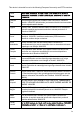
Modulation Technology Interface Brand Name Model Name FCC ID GSM HSDPA USB Modem (3G Card) HUAWEI E220 QISE220 GSM/UMTS 3G Card Sony Ericsson MD300 PY7F3232021 GSM 3G Card Band Luxe C100S UZI-C100 EC Conformance Declaration Marking by the above symbol indicates compliance with the Essential Requirements of the R&TTE Directive of the European Union (1999/5/EC).
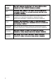
This device is intended for use in the following European Community and EFTA countries: Czech Estonian Eesti Käesolevaga kinnitab SMC seadme Radio LAN device vastavust direktiivi 1999/5/EÜ põhinõuetele ja nimetatud direktiivist tulenevatele teistele asjakohastele sätetele. English Hereby, SMC, declares that this Radio LAN device is in compliance with the essential requirements and other relevant provisions of Directive 1999/5/EC.
Lithuanian Maltese Malti Spanish Español Por medio de la presente SMC declara que el Radio LAN device cumple con los requisitos esenciales y cualesquiera otras disposiciones aplicables o exigibles de la Directiva 1999/5/CE Polish Polski Portuguese Português Slovak Slovensky Slovenian Slovensko x SMC declara que este Radio LAN device está conforme com os requisitos essenciais e outras disposições da Directiva 1999/5/CE.
About This Guide Purpose This guide details the hardware features of the wireless AP/Router, including its physical and performance-related characteristics, and how to install the device and use its configuration software. Audience This guide is for PC users with a working knowledge of computers. You should be familiar with Windows operating system concepts.
xii
Table of Contents Chapter 1: Introduction Package Checklist Hardware Description LED Indicators Ethernet RJ-45 Ports 3G Modem USB Port 3G Button Power Socket Reset Button WPS Button Chapter 2: Installation Router Mode AP Mode 1-1 1-1 1-2 1-4 1-5 1-5 1-5 1-5 1-6 1-6 2-1 2-1 2-2 Chapter 3: Network Planning 3-1 Internet Gateway Router LAN Access Point Wireless Client Wireless Bridge 3-1 3-2 3-3 3-4 Chapter 4: Initial Configuration Using the Setup Wizard Common Settings Static IP DHCP PPPoE 3G PPTP L2TP B
Contents Management IP WAN Setting WAN Connection Backup WAN Common Settings DHCP Static IP PPPoE 3G PPTP L2TP Bigpond Wi-Fi LAN Setting QoS Setting Wireless Settings Basic Settings Advanced Settings WLAN Security MAC Access Control Lists Wi-Fi Protected Setup (WPS) Routing Static Route Dynamic Route Multicast Routing Firewall NAT Packet Filtering URL Filter Security Setting Service Settings DHCP UPnP Setting DDNS Settings System Log Settings Date and Time Settings Ping Test Management Settings Admin Accoun
System Logs 3G Access History 5-68 5-69 Appendix A: Troubleshooting A-1 Appendix B: Specifications B-1 Appendix C: License Information C-1 The GNU General Public License Glossary Index C-1
Contents
Chapter 1: Introduction The SMCWBR14-3GN wireless AP/Router is an IEEE 802.11n wireless gateway router that connects your Internet access device (cable or ADSL modem) to your PC or local area network, or to its own secure wireless network. The wireless AP/Router can be automatically configured with other Wi-Fi Protected Setup (WPS) devices by simply pressing its WPS button. For more detailed configuration, the unit can also be set up through its easy-to-use web interface.
1 Introduction Hardware Description Power Socket Security Slot Reset Button Ethernet WAN RJ-45 Port Ethernet LAN RJ-45 Ports 3G Modem USB Port Figure 1-1.
Hardware Description 1 Antennas 3G Button WPS Button WLAN Button Figure 1-2. Front Panel AP/Router Mode Switch Figure 1-3.
1 Introduction LED Indicators The wireless AP/Router includes nine status LED indicators, as described in the following figure and table. LAN Link/Activity WAN Link/Activity Power 802.11n Link/Activity WPS Link/Activity 3G USB Link Figure 1-4. LED Indicators LED Status POWER On Green Indicates that the system is working normally. WAN On/Flashing Green Indicates a valid link on the WAN Ethernet port. Flashing indicates network activity. Off The Ethernet port has no valid link.
1 Hardware Description LED Status 3G USB Link On Description Indicates a connection through the attached 3G/3.5G USB modem. Fast Flashing Green* Indicates that the PIN code has failed. Ultra Fast Flashing Green** Indicates that 3G usage is already over the ISP supplied limit. Ultra Fast Flashing Green and OFF cycle every 5 seconds** Indicates that 3G usage is already over the user defined pre-warning limit. Slow Flashing Green Indicates that the 3G/3.5G USB modem is in the process of connecting.
1 Introduction Reset Button The Reset button can be used to restart the wireless AP/Router or restore the factory default configuration. If you press the button for less than 5 seconds, the wireless AP/Router will restart. If you press and hold down the button for 5 seconds or more, any configuration changes you may have made are removed and the wireless AP/Router is restored to its factory default configuration.
Chapter 2: Installation The wireless AP/Router has two basic operating modes that can be set through the switch on the bottom panel of the device: • Router Mode — Normal gateway mode that connects a wired LAN and wireless clients to an Internet access device, such as a cable or DSL modem. This is the factory set default mode. • AP Mode — An access point mode that extends a wired LAN to wireless clients.
2 Installation To connect the wireless AP/Router in Router Mode for use as an Internet gateway, follow these steps: 1. Connect an Ethernet cable from the wireless AP/Router’s WAN port to your Internet connected cable or ADSL modem. 2. Connect an Ethernet cable from the wireless AP/Router’s LAN port to your PC. Alternatively, you can connect to a workgroup switch to support multiple users. The wireless AP/Router can support up to 253 wired and wireless users. 3.
2 AP Mode Figure 2-2. AP Mode Connection To connect the wireless AP/Router for use as an access point, follow these steps: 1. Using Ethernet cables, connect the wireless AP/Router’s LAN and WAN ports to PCs or a LAN switch. 2. Power on the wireless AP/Router by connecting the AC power adapter and plugging it into a power source. Caution: Use ONLY the power adapter supplied with the wireless AP/Router. Otherwise, the product may be damaged.
2 2-4 Installation
Chapter 3: Network Planning The wireless AP/Router is designed to be very flexible in its deployment options. It can be used as an Internet gateway for a small network, or as an access point to extend an existing wired network to support wireless users. It also supports use as a wireless bridge to connect two wired LANs. This chapter explains some of the basic features of the wireless AP/Router and shows some network topology examples in which the device is implemented.
3 Network Planning The private local network, connected to the LAN port or wireless interface, provides a Dynamic Host Configuration Protocol (DHCP) server for allocating IP addresses to local PCs and wireless clients, and Network Address Translation (NAT) for mapping the multiple "internal" IP addresses to one "external" IP address.
3 Wireless Client Wireless Client The wireless AP/Router can operate as a wireless client on one VAP interface, which enables a connection to another Wi-Fi network. When the wireless client option is enabled as a WAN connection, the client VAP interface functions as an external gateway WAN port. When the wireless client option is enabled as a LAN connection, the other VAP interface and LAN ports all function as the local network within the same IP subnet. Figure 3-3.
3 Network Planning Wireless Bridge The IEEE 802.11 standard defines a Wireless Distribution System (WDS) for bridge connections between access points. The wireless AP/Router can use WDS to forward traffic on links between units. A single WDS bridge link can be specified for the WLAN1 interface. One end of a link must be configured as the “WDS Parent” and the other as the “WDS Child.” Note: The network domain of WDS child has to be the same as WDS parent. Figure 3-4.
Chapter 4: Initial Configuration The wireless AP/Router offers a user-friendly web-based management interface for the configuration of all the unit’s features. Any PC directly attached to the unit can access the management interface using a web browser, such as Internet Explorer (version 6.0 or above). This chapter describes the wireless AP/Router’s configurable features, all of which may be accessed through the web interface.
4 Initial Configuration Using the Setup Wizard There are only a few basic steps you need to set up the wireless AP/Router and provide a connection for network access for other wireless stations. The Setup Wizard takes you through configuration procedures for the general network settings. Follow these steps: 1. Launch the Setup Wizard – Click “Setup Wizard” on the left side of the screen to enter the setup wizard page. Click Next to begin the setup. Figure 4-2. Setup Wizard 2.
4 Using the Setup Wizard 3. WAN Configuration – Specifies the Internet connection parameters for the wireless AP/Router’s WAN port. Click Next after completing the setup. The interface provides the facility for Dual WAN connections for purposes of backing up the main internet connection. Figure 4-4. Setup Wizard - WAN Configuration The displayed items on this page are described in the sections that follow: WAN Connection — By default, the access point WAN port is configured with DHCP enabled.
4 Initial Configuration Common Settings The common settings for each WAN Connection mode are identical and are described in the section below. Figure 4-5. Common Settings WAN Ethernet MAC — Some ISPs limit Internet connections to a specified MAC address of one PC. This setting allows you to manually change the MAC address of the wireless AP/Router's WAN interface to match the PC's MAC address provided to your ISP for registration.
4 Using the Setup Wizard Static IP Configures a static IP for the WAN port. Figure 4-6. Setup Wizard - WAN Static IP • IP Address: The IP address of the wireless AP/Router. Valid IP addresses consist of four decimal numbers, 0 to 255, separated by periods. • Subnet Mask: The mask that identifies the host address bits used for routing to specific subnets.
4 Initial Configuration DHCP Enables Dynamic Host Configuration Protocol (DHCP) for the WAN port. This setting allows the wireless AP/Router to automatically obtain an IP address from a DHCP server normally operated by the Internet Service Provider (ISP). Figure 4-7.
4 Using the Setup Wizard PPPoE Enable the wireless AP/Router IP address to be assigned automatically from an Internet service provider (ISP) through an ADSL modem using Point-to-Point Protocol over Ethernet (PPPoE). Figure 4-8. Setup Wizard - WAN PPPoE • PPPoE Network Mode: Sets a PPPoE network mode. (Default: DHCP) • PPPoE IP Address: Sets the static IP address. (Default: 0.0.0.0, available when PPPoE Network Mode is set to static IP.) • PPPoE Username: Sets the PPPoE user name for the WAN port.
4 Initial Configuration 3G Enables a 3G/3.5G wide-area wireless cellular link on the WAN port using an optional USB modem. Note: To use this option you need to first connect a 3G/3.5G USB modem to the USB port on the back of the unit and have registered an account with a cellular operator. The following example shows the WAN function enabled with 3G.
4 Using the Setup Wizard The following cautionary message will appear each time you save your settings. Figure 4-10. Setup Wizard - WAN 3G PIN Code Warning An unauthenticated connection will display the message “Not dial yet” beneath the PIN code, as shown in the following example. Figure 4-11. Setup Wizard - WAN 3G Unauthenticated • Pin Code Protect: Enables the use of a PIN code (personal identification number) to encrypt access to the wireless 3G connection.
4 Initial Configuration • Dial Code: A dialled access code that connects the USB device to the service provider. • APN Service: The name that uniquely identifies the cellular operator, access point name (APN). • 3G Username: The username of the account registered with the service provider. • 3G Password: The password of the account registered with the service provider. • Connect Type: Selects the connection type as Keep Alive or Auto Connect.
Using the Setup Wizard 4 • Budget Policy: Enable or disable the action “Drop Current Cellular connection” or “Disallow New Cellular connection” if over budget. - Trigger by Limit Budget: - By Time: Set the specified percentage of time limit. - By Data: Set the specified percentage of data limit. - Action if Over Budget: Send an e-mail alert at the specified interval in minutes.
4 Initial Configuration • PPTP Network Mode: Sets a PPTP network mode. (Default: DHCP) • IP Address: Sets the static IP address. (Default: 0.0.0.0, available when PPTP Network Mode is set to static IP.) • Subnet Mask: Sets the static IP subnet mask. (Default: 255.255.255.0, available when PPTP Network Mode is set to static IP.) • Default Gateway: The IP address of the gateway router for the wireless AP/ Router, which is used if the requested destination address is not on the local subnet.
4 Using the Setup Wizard • L2TP Network Mode: Sets a L2TP network mode. (Default: DHCP) • IP Address: Sets the static IP address. (Default: 0.0.0.0, available when L2TP Network Mode is set to static IP.) • Subnet Mask: Sets the static IP subnet mask. (Default: 255.255.255.0, available when L2TP Network Mode is set to static IP.) • Default Gateway: The IP address of the gateway router for the wireless AP/ Router, which is used if the requested destination address is not on the local subnet.
4 Initial Configuration WiFi Enables a WAN connection to a normal remote AP over a wireless 802.11b/g/n connection. For this WAN setting, the wireless AP/Router operates as a Wi-Fi client to the remote AP. Figure 4-16. Setup Wizard - WAN WiFi • Wireless MTU: Sets the maximum packet size that the WAN port may transmit. The Maximum Transmission Unit (MTU) is expressed in bytes.
4 Using the Setup Wizard 4. WLAN Setting – Enables the wireless interface, selects the operating channel and configures SSIDs for both VAPs. Click Next after completing the setup. Figure 4-17. Setup Wizard - WLAN Configuration The displayed items on this page can be described as follows: • WLAN – Enables the communication for the VAP wireless interface. (Default: Enabled) • WLAN Mode – Defines the radio mode for the VAP interface. See “WLAN Mode” on page 5-23 for more information. (Default: 802.
4 5. Initial Configuration WLAN1/WLAN2 Security — Sets the wireless security encryption key for the wireless network. Figure 4-18. Setup Wizard - WLAN1 Security Authentication Mode – Configures the authentication mode used by clients. See “Authentication Mode” on page 5-29 for more information. (WLAN1/WLAN2 Defaults: Open) 6. Click Finish & Reboot after completing the configuration changes. Note that all configuration changes are not saved until the Setup Wizard is completed and the system has restarted.
Chapter 5: System Configuration The wireless AP/Router offers a user-friendly web-based management interface for the configuration of all the unit’s features. Any PC directly attached to the unit can access the management interface using a web browser, such as Internet Explorer (version 6.0 or above). This chapter describes the wireless AP/Router’s configurable features, all of which may be accessed through the web interface.
5 System Configuration The System Information page displays the System, Management IP, WAN, LAN, WLAN, and WDS settings. Figure 5-21.
5 The information in this chapter is organized to reflect the structure of the web management screens for easy reference. The Configuration pages include the options in the table below. For details on configuration for each feature, see the corresponding page number. Note: The displayed pages and settings may differ depending on whether the unit is in Router or AP Mode. Table 5-1.
5 System Configuration Table 5-1.
5 WAN Setting • Management IP Address – Specifies an IP address for management of the wireless AP/Router. Valid IP addresses consist of four decimal numbers, 0 to 255, separated by periods. (Default: 192.168.2.1.) • Subnet Mask – Indicates the local subnet mask. Select the desired mask from the drop down menu. (Default: 255.255.255.0) WAN Setting Specifies the Internet connection parameters. Click on “Network Settings” followed by “WAN.
5 System Configuration Common Settings Common Settings are the same for each WAN settings. This section describes the common parameters. Figure 5-23. WAN Common Settings (Router Mode) WAN Ethernet Speed — Configures the WAN Ethernet connection speed. (Default: Auto-Negotiated) • Auto-Negotiated – Enables auto-negotiation. • 100Mbps, Full-Duplex – Forces 100 Mbps full-duplex operation. • 100Mbps, Half-Duplex – Forces 100 Mbps half-duplex operation.
5 WAN Setting to identify network hosts by familiar names instead of the IP addresses. If you have one or more DNS servers located on the local network, type the IP addresses in the text fields provided. Otherwise, leave the addresses as all zeros (0.0.0.0). • Secondary DNS Server: The IP address of the Secondary Domain Name Server on the network. DHCP DHCP (Dynamic Host Control Protocol) is set as default for the primary WAN connection.
5 System Configuration Static IP Configures the unit to use the same IP address each time it connects. Figure 5-25. WAN Settings for Static IP (Router mode) Static IP — Configures a static IP for the WAN port. • Static IP MTU: Sets the maximum packet size that the WAN port may transmit. The Maximum Transmission Unit (MTU) is expressed in bytes.
WAN Setting 5 • WAN IP Alias – Adds more than one IP address to the network interface for multiple connectivity. - Enable: Enables the specified IP address. - Add: Specifies a WAN IP alias. - Change: Changes the already specified IP alias. - Delete: Deletes the IP alias. PPPoE Enable the wireless AP/Router IP address to be assigned automatically from an Internet service provider (ISP) through an ADSL modem using Point-to-Point Protocol over Ethernet (PPPoE). Figure 5-26.
5 System Configuration • PPPoE MRU: Sets the maximum packet size that the unit may receive from other units on the network and sends a message to inform them of the set threshold. Maximum Receive Unit (MRU) is expressed in bytes. (Default: 1492 bytes) Note: Only change the default MTU and MRU values if specifically instructed by the PPPoE service provider. • PPPoE Network Mode: Sets the PPPoE network mode to Static IP or DHCP.
5 WAN Setting 3G 3G technologies enable cellular network operators to offer users a wider range of more advanced services while achieving greater network capacity through improved spectral efficiency. Services include wide-area wireless voice telephony, video calls, and broadband wireless data, all in a mobile environment. To use the 3G option, you need to first connect a 3G/3.5G USB modem to the USB port on the back of the unit and have registered an account with a cellular operator. Figure 5-27.
5 System Configuration - Manually: If the 3G start mode is set to “Manually”, then you can only connect to the 3G Internet service by pressing the 3G button on the wireless AP/Router or by using the web interface. Figure 5-28. Manually Start 3G • Pin Code Protect: Enables the use of a PIN code (personal identification number) to encrypt access to the wireless 3G connection. Some service providers do not require PIN code authentication. If a PIN code is not required for your 3G/3.
5 WAN Setting • Budget Control: You can set a monthly limit on time or the total data. For more details, please refer to the following table. • Budget Criterion: - By Time: Specify the amount of time (in hours) that can be used per month. - By Data: Specify how much Download/Upload data (in MBytes) can be transmitted per month. • Budget Policy: Enable or disable the action “Drop Current Cellular connection” or “Disallow New Cellular connection” if over budget.
5 System Configuration PPTP Enable the Point-to-Point Tunneling Protocol (PPTP) for implementing virtual private networks. The service is provided in many European countries. Figure 5-29. WAN Settings for PPTP (Router mode) PPTP — Enable the Point-to-Point Tunneling Protocol (PPTP) for implementing virtual private networks. • PPTP MTU: Sets the maximum packet size that the WAN port may transmit. The Maximum Transmission Unit (MTU) is expressed in bytes.
5 WAN Setting • PPTP Username: Sets the PPTP user name for the WAN port. (Default: PPTP_USERNAME; Range: 1~32 characters) • PPTP Password: Sets a PPTP password for the WAN port. (Default: PPTP_PASSWORD; Range: 1~32 characters) • PPTP Server: Configures the IP address of the PPTP server interface. (Default: 0.0.0.0) L2TP Enable the Layer Two Tunneling Protocol (L2TP) for implementing virtual private networks. The service is provided in many European countries. Figure 5-30.
5 System Configuration • Only change the default MTU and MRU values if specifically instructed by the PPTP service provider. • L2TP Network Mode: Sets the L2TP IP address assignment to Static IP or DHCP. (Default: DHCP) • IP Address: Sets the static IP address as given by the L2TP service provider. (Default: 0.0.0.0, available when L2TP Network Mode is set to static IP.) • Subnet Mask: Sets the static IP subnet mask. (Default: 255.255.255.0, available when L2TP Network Mode is set to static IP.
5 WAN Setting Bigpond BigPond is an Australian Internet service provider, is a subsidiary of Telstra and owns a majority share of Internet access in Australia. Figure 5-31. WAN Settings for Bigpond (Router mode) Bigpond — Enables the settings of Telstra Bigpond network service in Australia. • Bigpond Username: Sets the Bigpond user name for the WAN port. (Default: BIGPOND_USERNAME; Range: 1~32 characters) • Bigpond Password: Sets a Bigpond password for the WAN port.
5 System Configuration Wi-Fi Enables a WAN connection to a normal remote AP over a wireless 802.11b/g/n connection. For this WAN setting, the wireless AP/Router operates as a Wi-Fi client to the remote AP. Figure 5-32. WAN Settings for Wi-Fi (Router mode) Wireless Client — Enables the WLAN1 VAP to act as a wireless connection to the WAN. • Wireless MTU: Sets the maximum transmission units in bytes. (Default: 1460 bytes) • Wireless MRU: Sets the maximum receive units in bytes.
LAN Setting 5 LAN Setting The wireless AP/Router must have a valid IP address for management using a web browser and to support other features. The unit has a default IP address of 192.168.2.1. You can use this IP address or assign another address that is compatible with your existing local network. Click on "Network Settings" followed by "LAN." Figure 5-33. LAN Settings (Router mode) • LAN IP Address – Valid IP addresses consist of four decimal numbers, 0 to 255, separated by periods.
5 System Configuration QoS Setting The QoS setting page is used to configure Quality of Service (QoS) for Traffic Prioritization and Bandwidth Management. Quality of Service (QoS) provides users the control over which type of outgoing data traffic is given priority by the router. The throughput rate of both the upload and download data passed through the wireless AP/Router can be throttled. Figure 5-34.
LAN Setting 5 • WAN Upload Bandwidth – Sets the maximum WAN upload bandwidth. (Default: 102400 kbps) • LAN Download Bandwidth – Sets the maximum LAN download bandwidth. (Default: 102400 kbps) Traffic Control QoS — The feature is applied when the applications use static ports to provide services. The wireless AP/Router can map traffic using specific TCP/UDP ports to one of the QoS priorities; low, medium, high, and highest. (Maximum 32 entries are allowed.
5 System Configuration Wireless Settings The IEEE 802.11n interfaces include configuration options for radio signal characteristics and wireless security features. The wireless AP/Router can operate in five modes, mixed 802.11b/g/n, mixed 802.11b/g, 802.11b only, 802.11g only or 802.11n only. Also note that 802.11g is backward compatible with 802.11b, and 802.11n is backward compatible with both 802.11b/g at slower data transmit rates.
5 Wireless Settings Choosing to reboot after making configuration changes triggers a countdown window that requires 60 seconds to complete. Figure 5-36. Implementing Changed Settings Basic Settings The Basic Setting page allows you to enable the wireless interface, select which radio mode to use, choose the transmit frequency and configure SSIDs. Click on "Wireless Settings," followed by "Basic Setting.
5 System Configuration - 802.11b/g Mixed: Both 802.11b and 802.11g clients can communicate with the wireless AP/Router (up to 108 Mbps), but data transmission rates may be slowed to compensate for 802.11b clients. Any 802.11n clients will also be able to communicate with the wireless AP/Router, but they will be limited to 802.11g protocols and data transmission rates. - 802.11b: All 802.11b, 802.11g, and 802.11n clients will be able to communicate with the wireless AP/Router, but the 802.11g and 802.
5 Wireless Settings Advanced Settings The Advanced Setting page allows you to configure the more advanced radio settings, many of which are enabled by default. Click “Wireless Settings” followed by “Advanced Setting.” Figure 5-38. Advanced Radio Settings • b/g Protection – Enables a backward compatible protection system for 802.11b clients. There are three modes. (Default: Auto): - Auto: The wireless AP/Router enables its protection mechanism for 802.11b clients when they are detected in the network.
5 System Configuration Note: Some 802.11n wireless clients may be capable of transmission rates of up to 600 Mbps, however the wireless AP/Router will only be able to connect to them at a maximum transmission rate of 300 Mbps. 802.11b/g packets are referred to as non-HT packets, being transmitted at lower throughput rates. HT mixed format frames contain a preamble compatible with the non-HT receivers. HT Greenfield frames do not contain a non-HT compatible part.
5 Wireless Settings WLAN Security The wireless AP/Router’s wireless interface is configured by default as an “open system,” which broadcasts a beacon signal including the configured SSID. Wireless clients with a configured SSID of “ANY” can read the SSID from the beacon, and automatically set their SSID to allow immediate connection to the wireless network.
5 System Configuration Figure 5-39. WLAN1 Settings Figure 5-40.
5 Wireless Settings Security Settings — The security settings determine the authentication mode and enable WEP keys. • Authentication Mode – Configures the authentication mode used by clients. (WLAN1/WLAN2 Defaults: Open) - Open: Open-system authentication accepts any client attempting to connect the wireless AP/Router without verifying its identity. In this mode the default encryption type is "None.
5 System Configuration - WPA Enterprise or WPA2 Enterprise: The WPA Enterprise mode uses IEEE 802.1X as its basic framework for user authentication and dynamic key management. IEEE 802.1X access security uses Extensible Authentication Protocol (EAP) and requires a configured RADIUS authentication server to be accessible in the enterprise network. If you select WPA or WPA2 Enterprise mode, be sure to configure the RADIUS settings. See “RADIUS” on page 5-32 for more information.
Wireless Settings 5 - TKIP/AES: Uses either TKIP or AES keys for encryption. WPA/WPA2 mixed modes allow both WPA and WPA2 clients to associate to a common SSID interface. In mixed mode, the unicast encryption cipher (TKIP or AES-CCMP) is negotiated for each client. • Default Key ID – Sets the WEP key used for authentication. (Default: 1; Range: 1~4) • Key 1 ~ Key 4 – Sets WEP key values. The user must first choose between ASCII or Hexadecimal keys. At least one key must be specified.
5 System Configuration exchange and association. Pre-authentication support attaches a security flag to the packet header. (Default: Disabled) RADIUS Remote Authentication Dial-in User Service (RADIUS) is an authentication protocol that uses software running on a central server to control access to RADIUS-aware devices on the network. An authentication server contains a database of user credentials for each user that requires access to the network.
5 Wireless Settings WDS Settings The WLAN1 radio interface can be configured to operate in a mode that allows it to forward traffic directly to other access point units. To set up links between access point units, you must configure the Wireless Distribution System (WDS) forwarding table by specifying the wireless MAC address of all units to which you want to forward traffic. Traffic forwarded to WDS links is automatically converted to 802.11 four-address format frame.
5 System Configuration WDS Setting — Configures WDS related parameters. Up to four MAC addresses can be specified for each unit in the WDS network. WDS links may either be manually configured (Bridge and Repeater modes) or auto-discovered (Lazy mode). • WDS – Selects the WDS mode of WLAN1. (Default: Disabled) - Disabled: WDS is disabled.
5 Wireless Settings - AES: Uses Advanced Encryption Standard (AES) keys for encryption. Use of AES-CCMP encryption is specified as a standard requirement for WPA2. Before implementing WPA2 in the network, be sure client devices are upgraded to WPA2-compliant hardware. - TKIP/AES: Use both TKIP and AES keys for encryption. WPA2 defines a transitional mode of operation for networks moving from WPA security to WPA2.WPA2 Mixed Mode allows both WPA and WPA2 clients to associate to a common SSID interface.
5 System Configuration - Open: Enables the AP/Router to connect to a Wi-Fi network that does not require any authentication. In this mode the default encryption type is "None." - Shared: The shared-key approach uses Wired Equivalent Privacy (WEP) to verify client identity by distributing a shared key to clients before attempting authentication.
Wireless Settings 5 Standard keys are either 5 or 13 alphanumeric characters; or 10 or 26 hexadecimal digits. (Default: ASCII, no preset value) • WPA/WPA2 Pre-Shared Key – This option is available only when Authentication Mode is set to WPA Personal, WPA2 Personal or WPA/WPA2 Personal. Enter a key as an easy-to-remember form of letters and numbers. The WDS WPA/WPA2 Preshared Key can be input as ASCII string (8-63 characters) or Hexadecimal format (length is 64).
5 System Configuration • Reset – Restores the previous MAC Access Policy configuration information. • Enable – Activates the MAC address into the ACL. • MAC Address – MAC Address to filter, specified in the form of 12 hexadecimal digits, “xx:xx:xx:xx:xx:xx”. • Description – An optional parameter to help identify the selected MAC address. (Range: 1~16 characters) • Action – Specifies an action to take on the MAC ACL filtering configuration.
5 Wireless Settings Wi-Fi Protected Setup (WPS) Wi-Fi Protected Setup (WPS) is designed to ease installation and activation of security features in wireless networks. WPS has two basic modes of operation, Push-button Configuration (PBC) and Personal Identification Number (PIN). The WPS PIN setup is optional to the PBC setup and provides more security. The WPS button on the wireless AP/Router can be pressed at any time to allow a single device to easily join the network.
5 System Configuration clients that were retained in memory. Only new clients will require authentication. (Default: Disabled) • Submit – Enables the WPS configuration. • Reset – Restores the previous WPS configuration information. AP Security Information — Provides detailed WPS statistical information. • WPS Configured – States if WPS for wireless clients has been configured for this device. (Default: no) • WPS Status – Displays if there is currently any WPS traffic connecting to the wireless AP/Router.
5 Routing • Add Enrollee PIN Code – In Registrar mode enter the PIN Code for the WDS device that wants to join the network. • PIN Code of this AP – In Enrollee mode this displays the PIN Code for the wireless AP/Router. The default is exclusive for each unit. • Start WPS Config – Sends a handshake beacon to devices wanting to join the network, for a duration of two minutes. Routing Routing setup allows a manual method that is used to set up routing between networks.
5 System Configuration - Edit: Click "Edit" to highlight an entry in the static MAC list for changing its parameters. - Delete: Deletes a static route from the list. Dynamic Route The wireless AP/Router supports RIP 1 and RIP 2 dynamic routing protocol. Routing Information Protocol (RIP) is the most widely used method for dynamically maintaining routing tables. RIP uses a distance vector-based approach to routing.
5 Routing Multicast Routing Multicasting is used to support real-time applications such as videoconferencing or streaming audio. A multicast server does not have to establish a separate connection with each client. It merely broadcasts its service to the network, and any hosts that want to receive the multicast register with their local multicast router.
5 System Configuration WAN Multicast Routing — IP addresses of upstream multicast routers on the WAN interface. You can add, edit, and delete IP addresses from the list. • IP Address – Specifies an IP address to route to. • Net Mask – Specifies a network mask. Firewall The wireless AP/Router provides extensive firewall protection by restricting connection parameters to limit the risk of intrusion and defending against a wide array of common hacker attacks.
5 Firewall Figure 5-49. NAT (Router mode) NAT Setting — Enables NAT related settings. • Network Address Translation – Enables the forwarding of TCP/UDP packets through a NAT device. • IPSec Pass Through – Enables tunnelling encrypted Internet Protocol Security (IPSec) packets through a NAT device. • PPTP Pass Through – Enables tunnelling Point-to-Point Tunneling Protocol (PPTP) packets through a NAT device.
5 System Configuration • DMZ LAN IP – Specifies the IP address of the DMZ. • Non-standard FTP port – Enables routing of traffic through a non-standard FTP port. • Submit – Saves the current NAT configuration. • Reset – Restores the previous NAT configuration information. Virtual Server Mapping — Using the NAT Virtual Server Mapping feature, remote users can access different servers on your local network using your single public IP address. (Maximum 32 entries are allowed.
5 Firewall - Add: Adds a newly configured port trigger to the list. - Edit: Click "Edit" to highlight a port trigger rule in the list for changing its parameters. - Delete: Deletes a port trigger rule from the list. Port Forward — Port forwarding (sometimes referred to as tunneling) is the act of forwarding a network port from one network node to another. This technique can allow an external user to reach a port on a private IP address (inside a LAN) from the outside through a NAT-enabled router.
5 System Configuration Packet Filtering The wireless AP/Router provides extensive firewall protection through packet filtering. Packet filtering restricts connection parameters to limit the risk of intrusion and defends against a wide array of common hacker attacks. Packet filtering allows the unit to permit, deny or proxy traffic through its ports. Figure 5-50. Packet Filtering (Router mode) WAN Packet Filter — Globally enables WAN packet filtering. (Default: Enabled, maximum 32 entries are allowed.
5 Firewall - Change: By selecting a packet filtering configuration from the table its parameters display in an editable form. Click "Change" to save parameters once you have updated them. - Add: Adds a newly configured packet filter that denies forwarding in to the local area network to the list. - Edit: Click "Edit" to highlight a packet filtering rule in the list for changing its parameters. - Delete: Deletes a packet filtering rule from the list.
5 System Configuration - Edit: Click "Edit" to highlight a preconfigured packet filtering rule for changing its parameters. - Delete: Deletes a packet filtering rule from the list. URL Filter By filtering inbound Uniform Resource Locators (URLs) the risk of compromising the network can be reduced. URLs are commonly used to point to websites. By specifying a URL or a keyword contained in a URL traffic from that site may be blocked. Click "Network Settings" followed by "URL Filter." Figure 5-51.
Firewall 5 Security Setting The Security Setting page enables intrusion detection (ID), a type of security management system for computers and networks. An ID system gathers and analyzes information from various areas within a computer or a network to identify possible security breaches, which include both intrusions (attacks from outside the organization) and misuse (attacks from within the organization).
5 System Configuration Service Settings DHCP The wireless AP/Router includes a Dynamic Host Configuration Protocol (DHCP) server that can assign temporary IP addresses to any attached host requesting the service. The unit can support up to 253 local clients. Addresses are assigned to clients from a common address pool configured on the unit. Configure an address pool by specifying start and end IP addresses. Be sure not to include the unit's IP address in the address pool range.
5 Service Settings • DHCP Static Map – Maps client MAC addresses to static IP addresses. This allows specified clients to always be assigned the same IP when they request settings. (Maximum 32 entries are allowed.) - MAC: The physical layer address used to uniquely identify the static IP address to be assigned to the specified client MAC address. The IP address must be in the same subnet as the wireless AP/Router.. - IP: The static IP address to be assigned to the specified client MAC address.
5 System Configuration UPnP Setting UPnP (Universal Plug and Play) provides inter-connectivity between devices supported by the same standard. UPnP is based on standard Internet protocols, such as TCP/IP, UDP, and HTTP. Click on “Network Settings” followed by “UPnP.” Figure 5-54. UPnP Setting (Router mode) UPnP Setting — Allows the device to advertise its UPnP capabilities. • UPnP Internet Gate Device – Enables UPnP on the wireless AP/Router.
5 Service Settings DDNS Settings Dynamic DNS (DDNS) provides users on the Internet with a method to tie a specific domain name to the unit’s dynamically assigned IP address. DDNS allows your domain name to follow your IP address automatically by changing your DNS records when your IP address changes. The wireless AP/Router provides access to three DDNS service providers, DynDns.org, Non-IP.com and ZoneEdit.com. To set up an DDNS account, visit the websites of these service providers at www.dyndns.
5 System Configuration System Log Settings The wireless AP/Router supports a logging process that controls error messages saved to memory or sent to a Syslog server. The logged messages serve as a valuable tool for isolating wireless AP/Router and network problems. The System Log Settings page controls the type of logging message that the wireless AP/Router can send. Figure 5-56. System Log Settings • System Log – Enables local storage of system logs concerned with the wireless AP/Router only.
5 Service Settings • Total Log Size – Indicates the amount of RAM or Flash memory available for logging messages. (Default: 10 Kbytes; Range: 10 or 20 Kbytes) • Remote Log – Enables remote storage of system logs on a Syslog server. (Default: Disabled) • Remote Log Server Address – The address of the remote logging server. (Default: your.syslog.server) • Remote Log Server Port – The remote port to which messages are to be sent to.
5 System Configuration • Daylight Saving – Enables daylight savings for summertime. Daylight Saving Time begins for most of the United States at 2:00 a.m. on the first Sunday of April. Time reverts to standard time at 2:00 a.m. on the last Sunday of October. In the U.S., each time zone switches at a different time. In the European Union, Summer Time begins and ends at 1:00 a.m. GMT. It begins the last Sunday in March and ends the last Sunday in October. In the EU, all time zones change at the same moment.
5 Service Settings Ping Test The wireless AP/Router provides the function of “pinging” a specified IP address or URL to test for connectivity. Figure 5-59. Ping Test - success Figure 5-60. Ping Test - failure • PING Destination – The destination IP address to test. • PING – Sends the request.
5 System Configuration Management Settings The wireless AP/Router’s Management Settings menu provides the same configuration options in both Router and AP Mode. These settings allow you to change the operating mode, set the system time, configure a management access password, and upgrade the system software. Admin Accounts and Remote Administration Management access to the wireless AP/Router is controlled through different levels of user name and password.
5 Management Settings Admin Accounts — Configures access levels, usernames and passwords. (Maximum 32 entries are allowed.) • Access Level – Configures the access privileges that the user has. - Admin: Grants administrator level access, no restrictions. - User: Grants user level access, some restrictions. - Guest: Grants guest level access, configuration settings may not be changed.
5 System Configuration Config Settings The Config Setting page allows you to save the wireless AP/Router’s current configuration or restore a previously saved configuration back to the device. Figure 5-62. Config Settings • Save – Saves the current configuration locally. • Restore – Restores a previously saved configuration from a specified file. • Factory Default – Restores the factory defaults. • View Current Config – Opens a display window that details parameters about the current configuration.
5 Status Information Firmware Upgrade You can update the wireless AP/Router firmware by using the Firmware Update facility. Figure 5-64. Firmware Upgrade Firmware Update — Allows you to upload new firmware manually by specifying a file path. Make sure the firmware you want to use is on the local computer by clicking Browse to search for the firmware to be used for the update. • Browse – Opens a directory on the local hard drive for specifying the path of the file to upload.
5 System Configuration • Model Name – The device name and model number. • Firmware Version – The version number of the current wireless AP/Router software. • Host Name – The web address assigned as an alias for the wireless AP/Router, enabling the device to be uniquely identified on the network. • System Date – The current date and time set for the wireless AP/Router, in the form year; month; day; hours; minutes; seconds.
5 Status Information • Gateway Address – The default gateway is the IP address of the router for the wireless AP/Router, which is used if the requested destination address is not on the local subnet • DNS 1 (Primary) / DNS 2 (Secondary) – The IP address of Domain Name Servers on the network. A DNS maps numerical IP addresses to domain names and can be used to identify network hosts by familiar names instead of the IP addresses. Figure 5-67.
5 System Configuration WLAN — Displays the basic WLAN information: • WLAN Status –Displays if the radio is enabled or disabled. • Country – The country for which the wireless AP/Router has been set for use. • WLAN Mode – Displays the radio mode being used. • Frequency – The channel frequency being used by the radio. • WLAN1 SSID – The service set identifier for WLAN1. (Default: SMC) • WLAN1 MAC Address – The physical layer address for WLAN1. Figure 5-70.
5 Status Information • Flags – Possible flags include: U: route is up, H: target is a host, G: use gateway, C: cache entry, !: Reject route. • Metric – A number used to indicate the cost of the route so that the best route, among potentially multiple routes to the same destination, can be selected. • Ref – Number of references to this route. • Use – Count of lookups for the route. • Iface – Interface to which packets for this route will be sent.
5 System Configuration System Logs The wireless AP/Router supports a logging process that controls error messages saved to memory or sent to a Syslog server. The logged messages serve as a valuable tool for isolating wireless AP/Router and network problems. The Events Log page displays the latest messages logged in chronological order, from the newest to the oldest. Log messages saved in the wireless AP/Router’s memory are erased when the device is rebooted. Figure 5-73.
Status Information 5 • Refresh – Refreshes the System Log display to display the most recent messages received. • Date Time – The date and time of receival of the system log message. • Facility Priority – The priority level of the system log message. • Category – The category of system log message. • Info – Additional informative content that may help isolate the cause of the problem that prompted the system log message. 3G Access History Displays the budget control parameters and 3G access statistics.
5 System Configuration • When the time limit is over the budget. Figure 5-76.
Appendix A: Troubleshooting Check the following items before you contact local Technical Support. 1. If wireless clients cannot access the network, check the following: • Be sure the access point and the wireless clients are configured with the same Service Set ID (SSID). • If authentication or encryption are enabled, ensure that the wireless clients are properly configured with the appropriate authentication or encryption keys. 2.
A Troubleshooting Diagnosing LED Indicators Troubleshooting Chart Symptom Action POWER LED is Off • The AC power adapter may be disconnected. Check connections between the wireless AP/Router, the power adapter, and the wall outlet. WLAN LED is Off • The wireless AP/Router’s radio has been disabled through it’s web management interface. Access the management interface using a web browser to enable the radio.
Appendix B: Specifications Operating Frequency 802.11g/n: 2.4 ~ 2.4835 GHz (US, Canada) 2.4 ~ 2.4835 GHz (ETSI, Japan) 2.412 ~ 2.462 GHz (Taiwan) 802.11b: 2.4 ~ 2.4835 GHz (US, Canada) 2.4 ~ 2.4835 GHz (ETSI) 2.4 ~ 2.497 GHz (Japan) 2.412 ~ 2.462 GHz (Taiwan) Data Rate 802.11b: 1, 2, 5.5, 11 Mbps per channel 802.11g: 6, 9, 12, 18, 24, 36, 48, 54 Mbps per channel 802.11n: 27, 54, 81, 108, 162, 216, 243, 270, 300 Mbps per channel (40MHz) Operating Channels 802.11b/g and 802.11n (20MHz): 11 channels 802.
B Specifications EN 55022B EN 55024 EN61000-3-2 EN61000-3-3 Radio Signal Certification FCC Part 15C 15.247, 15.207 (2.4 GHz) EN 300 328 EN 301 489-1 EN 301 489-17 Standards IEEE 802.11b/g IEEE 802.11n draft v2.0 Physical Size 21.0 x 16.5 x 4.0 cm (8.27 x 6.50 x 1.57 in) Weight 350 g (12.
Appendix C: License Information This product includes copyrighted third-party software subject to the terms of the GNU General Public License (GPL), GNU Lesser General Public License (LGPL), or other related free software licenses. The GPL code used in this product is distributed WITHOUT ANY WARRANTY and is subject to the copyrights of one or more authors. For details, refer to the section "The GNU General Public License" below, or refer to the applicable license as included in the source-code archive.
C License Information We protect your rights with two steps: (1) copyright the software, and (2) offer you this license which gives you legal permission to copy, distribute and/or modify the software. Also, for each author's protection and ours, we want to make certain that everyone understands that there is no warranty for this free software.
The GNU General Public License C a). You must cause the modified files to carry prominent notices stating that you changed the files and the date of any change. b). You must cause any work that you distribute or publish, that in whole or in part contains or is derived from the Program or any part thereof, to be licensed as a whole at no charge to all third parties under the terms of this License. c).
C License Information c). Accompany it with the information you received as to the offer to distribute corresponding source code. (This alternative is allowed only for noncommercial distribution and only if you received the program in object code or executable form with such an offer, in accord with Subsection b above.) The source code for a work means the preferred form of the work for making modifications to it.
The GNU General Public License C consequence you may not distribute the Program at all. For example, if a patent license would not permit royalty-free redistribution of the Program by all those who receive copies directly or indirectly through you, then the only way you could satisfy both it and this License would be to refrain entirely from distribution of the Program.
C License Information NO WARRANTY 1. BECAUSE THE PROGRAM IS LICENSED FREE OF CHARGE, THERE IS NO WARRANTY FOR THE PROGRAM, TO THE EXTENT PERMITTED BY APPLICABLE LAW. EXCEPT WHEN OTHERWISE STATED IN WRITING THE COPYRIGHT HOLDERS AND/OR OTHER PARTIES PROVIDE THE PROGRAM "AS IS" WITHOUT WARRANTY OF ANY KIND, EITHER EXPRESSED OR IMPLIED, INCLUDING, BUT NOT LIMITED TO, THE IMPLIED WARRANTIES OF MERCHANTABILITY AND FITNESS FOR A PARTICULAR PURPOSE.
Glossary 10BASE-T IEEE 802.3-2005 specification for 10 Mbps Ethernet over two pairs of Category 3 or better UTP cable. 100BASE-TX IEEE 802.3-2005 specification for 100 Mbps Fast Ethernet over two pairs of Category 5 or better UTP cable. Access Point An internetworking device that seamlessly connects wired and wireless networks. Access points attached to a wired network, support the creation of multiple radio cells that enable roaming throughout a facility.
Glossary Encryption Data passing between the access point and clients can use encryption to protect from interception and evesdropping. Ethernet A popular local area data communications network, which accepts transmission from computers and terminals. File Transfer Protocol (FTP) A TCP/IP protocol used for file transfer. Hypertext Transfer Protocol (HTTP) HTTP is a standard used to transmit and receive all data over the World Wide Web. IEEE 802.
Glossary Open System A security option which broadcasts a beacon signal including the access point’s configured SSID. Wireless clients can read the SSID from the beacon, and automatically reset their SSID to allow immediate connection to the nearest access point. Orthogonal Frequency Division Multiplexing (ODFM) OFDM allows multiple users to transmit in an allocated band by dividing the bandwidth into many narrow bandwidth carriers.
Glossary Virtual Access Point (VAP) Virtual AP technology multiplies the number of Access Points present within the RF footprint of a single physical access device. With Virtual AP technology, WLAN users within the device’s footprint can associate with what appears to be different access points and their associated network services. All the services are delivered using a single radio channel, enabling Virtual AP technology to optimize the use of limited WLAN radio spectrum.
Index A H AC power adapter 1-5 ACL configuration 5-37 administrator accounts 5-61 administrator password 5-61 administrator username 5-61 Advanced Setting menu 5-25 AES 5-30, 5-35, 5-36 AP mode 2-1, 2-2 authentication mode 4-16, 5-29, 5-34, host name 5-6, 5-64 5-35 B bridge 3-4, 5-34 C channels, maximum B-1 clients, maximum B-1 contents, package 1-1 D DDNS 5-55 DHCP client list 5-53 DHCP server 5-8, 5-52 DHCP server address 5-64 DMZ 5-45 I IEEE 802.11n 1-1 IEEE 802.
Index URLs 5-50 S secondary DNS server 4-4, 5-7 software displaying version 5-56 static IP 4-5, 5-7 subnet mask 4-5, 5-5, 5-19, 5-64 system Information 5-63 system log 5-68 T time zone 5-57 TKIP 5-30, 5-34, 5-36 troubleshooting A-1, C-1 U UPnP 5-54 URL filter 5-50 Index-2 V virtual server mapping 5-46 W WAN packet filter 5-48 WAN setting 5-5 WDS MAC list 5-35 WDS settings 5-33 WEP 5-27, 5-29, 5-30, 5-34, 5-36 WLAN setting 4-15, 5-23 WPA/WPA2 5-27, 5-29 WPS 5-39 WPS button 1-6 WPS, PBC 5-40 WPS, PIN 5
SMCWBR14-3GN 20 Mason • Irvine, CA 92618 • Phn: 949-679-8000 • www.smc.com 20 Mason • Irvine, CA 92618 • Phn: (949) 679-8000 • www.smc.