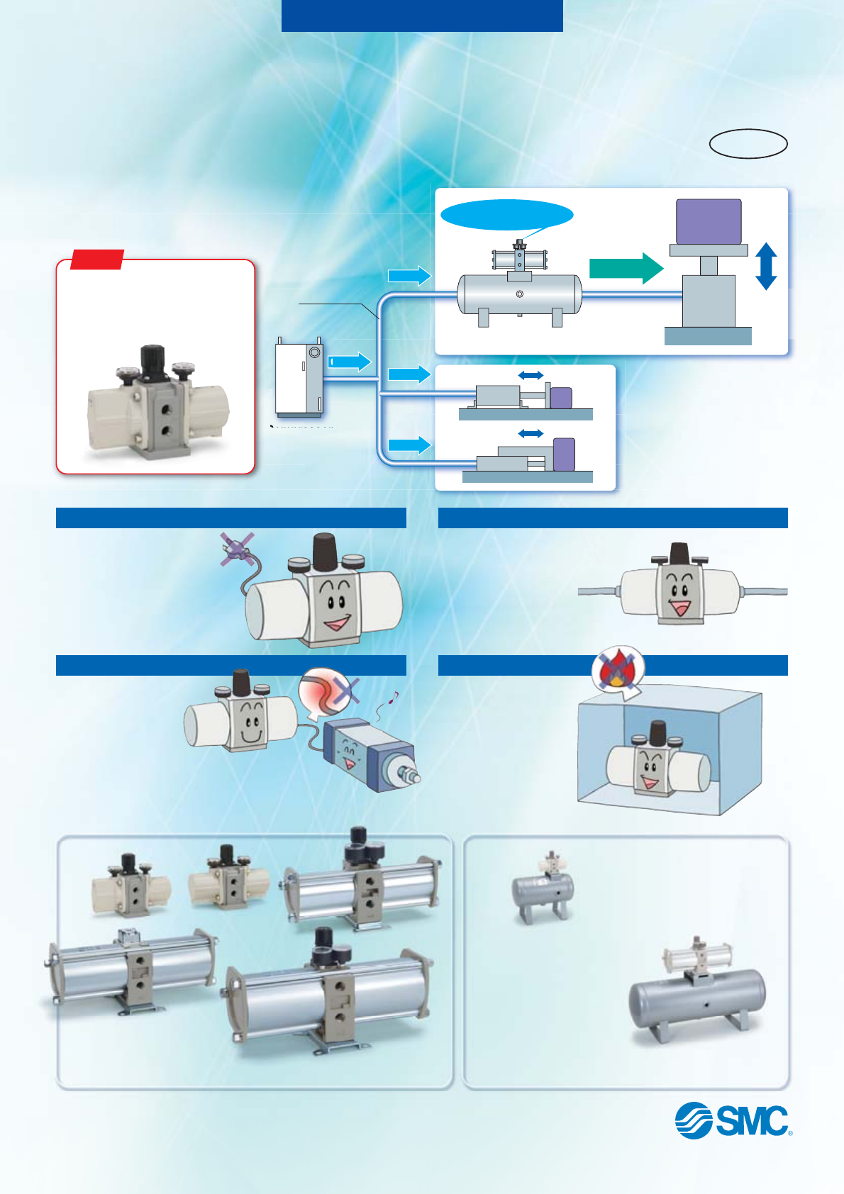
Booster Regulator/Air Tank New Increase factory air pressure by up to 4 times! Air-only operation requires no power supply, reduces heat generation, and Boost pressure allows easy installation. NEW Renewed model with pressure increase ratio 2 to 4 times (VBA11A) RoHS Heavy 0.6 MPa 0.3 MPa Factory line Booster Regulator + Air Tank 0.3 MPa 0.3 MPa Light Compressor 0.3 MPa Light No power supply or wiring needed There is no need to install dedicated electrical wiring.
Booster Regulator Series VBA Doubled 13 Reduced by dB (A) compared with the conventional model Improved service life that of the conventional model Reduced noise • Floating piston structure (PAT.
P. 1 Twice Pressure increase ratio Handle-operated type (Direct operation) Operation Set pressure range 0.2 to 1.0 MPa 0.2 to 1.6 MPa (2.0 MPa) Body size 2 to 4 times Air-operated type (Remote operation) Handle-operated type (Direct operation) 0.2 to 1.0 MPa 0.2 to 2.0 MPa VBA10A-02 VBA11A-02 (0.2 to 2.0 MPa) 1/4" VBA20A-03 VBA22A-03 3/8" VBA43A-04 VBA40A-04 VBA42A-04 (0.2 to 1.6 MPa) 1/2" Air Tank P.
Booster Regulator Series VBA RoHS Made to Order How to Order VBA 40A (For details, refer to page 11.) 04 Semi-standard Body size Symbol Semi-standard Standard product Pressure unit on the product name Z Note) label and pressure gauge: psi 10A 20A 40A 22A 42A 43A 1/4", Handle-operated type 3/8", Handle-operated type Pressure increase 1/2", Handle-operated type ratio: Twice 3/8", Air-operated type 1/2", Air-operated type 1/2", Max. operating pressure 1.
Series VBA Booster Regulator Standard Specifications VBA10A-02 Model VBA20A-03 VBA40A-04 VBA22A-03 Fluid VBA42A-04 VBA43A-04 VBA11A-02 Compressed air Pressure increase ratio 2 to 4 times Twice Pressure adjustment mechanism Set pressure range (MPa) Air-operated Handle-operated with relief mechanism Note 1) Max. flow rate Note 2) (L/min (ANR)) 1000 230 1900 1000 0.2 to 1.0 0.2 to 2.0 Handle-operated with relief mechanism Note 1) 1900 0.2 to 1.
Series VBA VBA10A VBA20A, 22A VBA40A, 42A Flow-rate Characteristics Flow-rate Characteristics Flow-rate Characteristics P1 =1 MP a P1 Outlet pressure (MPa) Outlet pressure (MPa) .0 1.5 =0 .75 MP a 1 P1 P1 P1 .5 .4 =0 .3 0.5 =0 =0 MP MP a P1 = P2 a MP a 0 100 1.0 1.0 0.8 0.8 0.6 P1 = 0.5 MPa 0.4 P1 = 0.4 MPa P1 = 0.3 MPa 0.2 200 300 400 0 400 600 800 Set point 0 0.9 0.85 Inlet pressure: 0.7 MPa (Representative Outlet pressure: 1.
Series VBA Booster Regulator Pulsation/Pulsation is decreased with a tank. VBA43A VBA11A Flow-rate Characteristics Flow-rate Characteristics If the outlet capacity is undersized, pulsation may occur. VBAT05A 2 1.6 0.1 Outlet pressure (MPa) Max. pulsation range (MPa) 1. 0 Pa M 75 0. M Pa P1 = P2 a MP Pa a M .3 MP .4 P1 = P2 0.4 =0 a 0.6 1 .5 MP a =0 MP = .6 5 P1 0. MP a MP a =0 = =0 .8 =0 .7 =0 P1 P1 0.8 P1 P1 1 = P1 P1 P1 1.
Series VBA Sizing can be achieved with the SMC Pneumatic System Energy Saving Program Ver. 4.0.06 ( Sizing ) which can be downloaded from the SMC website: http://www.smcworld.com/ P3 P2 Ts Stroke P1 L Tc øD Pressure Upper limit of pressure inside the tank P3 Necessary supply pressure to cylinder P2 Lower limit of pressure inside the tank P2 Inlet pressure P1 START Time Necessary conditions: D [mm]: Cylinder bore size L [mm]: Cylinder stroke W [mm/s]: Cylinder operating speed C [pc.
Booster Regulator Series VBA Working Principle The IN air passes through the check valve to booster chambers A and B. Meanwhile, air is supplied to drive chamber B via the governor and the switching valve. Then, the air pressure from drive chamber B and booster chamber A are applied to the piston, boosting the air in booster chamber B. As the piston travels, the boosted air is pushed via the check valve to the OUT side.
Series VBA Design Mounting Caution Warning 1. Warning concerning abnormal outlet pressure • If there is a likelihood of causing an outlet pressure drop due to unforeseen circumstances such as equipment malfunction, thus leading to a major problem, take safety measures on the system side. • Because the outlet pressure could exceed its set range if there is a large fluctuation in the inlet pressure, leading to unexpected accidents, take safety measures against abnormal pressures.
Booster Regulator Series VBA Handling Caution 1. Setting the pressure on the handle-operated type • If air is supplied to the product in the shipped state, the air will be released. Set the pressure by quickly pulling up on the governor handle, releasing the lock, and rotating the handle in the direction of the arrow (+). • There is an upper and lower limit for the handle rotation. If over-rotating the handle even after reaching to the limit, the internal parts may be damaged.
Series VBA Construction/Replacement Parts VBA10A VBA11A 햳 햶 햲 햵 햴 VBA20A, 22A, VBA40A, 42A, 43A 햵 햴 햷 햳 햶 햲 Air-operated type 햲 햶 햲 햷 햵 햳 햴 VBA22A, 42A Replacement Parts/Kit No. Place an order with the following applicable kit number. Model VBA10A VBA20A VBA40A VBA22A VBA42A VBA43A VBA11A Kit no.
Booster Regulator Series VBA Dimensions VBA10A-02 With elbow silencer (Option) Pressure gauge (Option) 60 IN side gauge port Rc 1/8 OUT side gauge port Rc 1/8 7 28 27 23 113 Silencer (Option) IN port Rc 1/4 OUT port Rc 1/4 22 4 x ø5.5 40 EXH port Rc 1/4 60 70 50 IN port Rc 1/4 OUT port Rc 1/4 60 4 x ø5.5 8.
Series VBA Dimensions VBA22A-03 300 28 Pressure gauge (Option) 39 OUT side gauge port Rc 1/8 43 IN port Rc 3/8 15 OUT port Rc 3/8 21 Silencer (Option) 24 98 4 x ø12 118 EXH port Rc 3/8 53 73 (When silencer installed: 179) (When high-noise reduction silencer installed: 179) 43 VBA42A-04 3.
Air Tank Series VBAT RoHS Made to Order How to Order • Compact connections are possible with booster regulators. • It can be used alone as a tank. VBAT 10 A F SV Q CE certified product (Self-declaration document attached) Tank internal capacity Symbol Internal capacity 5L 05 10 L 10 20 L 20 38 L 38 Material Symbol A VBAT05A (For details, refer to page 13.
Series VBAT Specifications Design VBAT05A 쏔-SV-Q Model VBAT10A 쏔-SV-Q VBAT20A 쏔-RV-Q VBAT38A 쏔-SV-Q Compressed air Fluid 5 Tank capacity (L) 10 Max. operating pressure (MPa) 20 38 2.0 1.0 IN port size 3/8 1/2 3/4 3/4 OUT port size 3/8 1/2 1/2 3/4 10 14 Carbon steel (SS400) 21 0 to 75 Ambient and fluid temperature (°C) 6.6 Weight (kg) Material • Operate this product below the maximum operating pressure.
Series VBAT Air Tank Dimensions VBAT05A-Q Material: Carbon steel Connected to VBA10A, 11A Safety valve port Rc 3/8 Tank IN port Rc 3/8 Booster regulator IN port Rc 1/4 Spare port 2 x Rc 1/2 (370) EXH: Rc 1/4 257 Tank OUT port Rc 3/8 56 ø1 4 x ø11 163 (307) 60 60 OUT 32 32 Drain port Rc 1/4 100 160 200 338 360∗ ∗ The length may be longer than the specification if the plugs mounted on the tank are not fit to the end.
Series VBAT Dimensions: CE Certified Product VBAT20A-Q Material: Carbon steel Connected to VBA20A, 40A Connected to VBA22A, 42A Tank IN port Rc 3/4 Safety valve port Rc 3/8 Booster regulator IN port Booster regulator IN port C C 305 Tank OUT port Rc 1/2 180 06 ø2 4 x ø13 (B) OUT D EXH: C Spare port 2 x Rc 1/2 250 (A) (A) (B) EXH: C 06 ø2 50 Drain port Rc 1/4 100 200 OUT 4 x ø13 50 400 100 674 200 696∗ (mm) ∗ The length may be longer than the specification if the plugs mounte
16
Safety Instructions Caution: Warning: Danger : These safety instructions are intended to prevent hazardous situations and/or equipment damage. These instructions indicate the level of potential hazard with the labels of “Caution,” “Warning” or “Danger.” They are all important notes for safety and must be followed in addition to International Standards (ISO/IEC)∗1), and other safety regulations.