
Datasheet


Design
Warning
1. Warning concerning abnormal outlet pressure
• If there is a likelihood of causing an outlet pressure drop
due to unforeseen circumstances such as equipment
malfunction, thus leading to a major problem, take safety
measures on the system side.
• Because the outlet pressure could exceed its set range if
there is a large fluctuation in the inlet pressure, leading to
unexpected accidents, take safety measures against abnor-
mal pressures.
• Operate the equipment within its maximum operating
pressure and set pressure range.
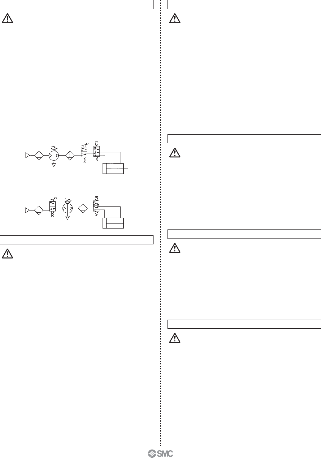
2. Residual pressure measures
• Connect a 3-port valve to the OUT side of the booster
regulator if the residual pressure must be released quickly
from the outlet pressure side for maintenance, etc. (Refer to
the diagram below.) The residual outlet pressure side
cannot be released even if the 3-port valve is connected to
the IN side because the check valve in the booster regulator
will activate.
• After operation is finished, release the supply pressure at
the inlet. This stops the booster regulator from moving
needlessly and prevents operating malfunctions.
Selection
Caution
1. Check the specifications.
• Consider the operating conditions and operate this product
within the specification range that is described in this
catalogue.
2. Selection
•
Based on the conditions (such as pressure, flow rate and cycle time) required for
the outlet side of the booster regulator, check the selection procedures described
in this catalog or model selection software for size selection of the booster
regulator.
•
Since the booster regulator is a compressor powered by the air, it consumes the
air. The air consumption is approximately 1.2 times (pressure increase ratio 2) or
2.7 times (pressure increase ratio 4) larger than the outlet side volume.
Therefore, the booster regulator requires a supply capacity of the inlet side
volume that is approximately 2.2 times (pressure increase ratio 2) or 3.7 times
(pressure increase ratio 4) larger than the outlet side volume.
•
Set the pressure of the VBA10A, VBA20A, VBA22A, VBA40A, VBA42A or
VBA43A (pressure increase ratio 2) to a level that is at least 0.1 MPa higher than
the inlet pressure. If the pressure differential is 0.1 MPa or less, the internal
operating pressure becomes the minimum operating pressure or less and the
switching valve may remain at the intermediate position, causing a restart failure.
•
Set the pressure increase ratio of the VBA11A (pressure increase ratio 4) to 2 or
more. When the VBA11A is used at a pressure increase ratio of 2 or less, the
internal operating pressure becomes the minimum operating pressure or less and
the switching valve may remain at the intermediate position, causing a restart
failure.
•
When operating the booster regulator continuously for longer periods of time,
particularly confirm its service life.
•
The service life of the booster regulator depends on not the operation hours but
the operating cycles (piston sliding distance). The operating cycles (piston sliding
distance) depend on the outlet flow of the booster regulator. Thus, when more
outlet flow of the booster regulator is used, its service life becomes shorter.
Mounting
Caution
1. Transporting
• When transporting this product, hold it lengthwise with both
hands. Never hold it by the black handle that protrudes from
the center because the handle could become detached
from the body, causing the body to fall and leading to injury.
2. Installation
• Install this product so that the silver-coloured tie-rods and
cover are placed horizontally. If mounted vertically, it may
result in a malfunction.
• Because the piston cycle vibration is transferred, use the
following mounting bolts (VBA1: M5; VBA2, 4: M10) and
tighten them with the specified torque (VBA1: 3 N·m; VBA2,
4: 24 N·m).
• If the transmission of vibration is not preferred, insert an
isolating rubber material before installation.
• Mount the pressure gauge with a torque of 7 to 9 N·m.
Piping
Caution
1. Flushing
• Use an air blower to flush the piping to thoroughly remove
any cutting chips, cutting oil, or debris from the piping
inside, before connecting them. If they enter the inside of
the booster regulator, they could cause the booster regula-
tor to malfunction or its durability could be affected.
2. Piping size
• To bring the booster regulator’s ability into full play, make
sure to match the piping size to the port size.
Air Supply
Caution
1. Quality of air source
• Connect a mist separator to the inlet side near the booster
regulator. If the quality of the compressed air is not
thoroughly controlled, the booster regulator could malfunc-
tion (without being able to boost) or its durability could be
affected.
• If dry air (atmospheric pressure dew point: –17°C or less) is
used, the life expectancy may be shortened because dry air
will accelerate evaporation of grease inside.
Operating Environment
Caution
1. Installation location
• Do not install this product in an area that is exposed to
rainwater or direct sunlight.
• Do not install in locations influenced by vibrations. If it must
be used in such an area due to unavoidable circumstances,
please contact SMC beforehand.
Series VBA
7