
Datasheet


Specifications
Booster regulator
VBA2쏔AVBA1쏔A VBA4쏔A
쎲
쎲
—
—
쎲
쎲
쎲
쎲
쎲
—
—
—
1. Operating pressure
• Operate this product below the maximum operat-
ing pressure. If it is necessary, take appropriate
safety measures to ensure that the maximum op-
erating pressure is not exceeded.
• When the tank alone is used
Use a pressure switch or a safety valve to ensure
that the maximum operating pressure is not ex-
ceeded.
2. Connection
• Connect a filter or a mist separator to the OUT
side of the tank. Because the inner surface of the
tank is untreated, there is a possibility of dust
flowing out to the outlet side.
• A VBA booster regulator can be connected
directly with the tank accessories as indicated
combinations below.
• Consider the operating conditions and operate
this product within the specification range.
• When using the air tank with a booster regulator,
refer to “Sizing” on page 5 or SMC Pneumatic
System Energy Saving Program.
Warning
Caution
Design
Selection
Caution
1. Accessories
• Refer to the operation manual (VBAT-M1, M2,
M3, M4) regarding combining booster regulators
with older model air tanks.
• The accessories are secured by bands to the feet
of the air tank. Once removed, make sure not to
lose them.
2. Installation
• Install the tank away from people. It is dangerous
if the accumulated air inside the tank were to
seep out.
• Do not mount the air tank on a moving part or a
place with vibration.
• When connecting a booster regulator with the
tank, refer to the operation manual first, which is
provided with the air tank before assembling.
• Refer to the operation manual regarding mount-
ing methods when using long bolts.
• To mount the air tank on a floor surface, use the
four holes to secure the tank with bolts or anchor
bolts.
Mounting
Warning
1. Inspection
• The use of pressure vessels could lead to an un-
expected accident due to external damage or
internal corrosion caused by drainage. Therefore,
make sure to check periodically for external
damage, or the extent of internal corrosion
through the port hole. An ultrasonic thickness
indicator may also be used to check for any re-
duction in material thickness.
2. Draining
• If this product is used with a large amount of
drainage, the drainage could flow out, leading to
equipment malfunction or corrosion inside the
tank. Therefore, drain the system once a day.
Maintenance
VBAT05A
VBAT10A
VBAT20A
VBAT38A
Model
VBAT05A
쏔-SV-Q
VBAT10A
쏔-SV-Q
VBAT20A
쏔-RV-Q
VBAT38A
쏔-SV-Q
Fluid
Tank capacity (L)
Max. operating pressure
(MPa)
IN port size
OUT port size
Ambient and fluid temperature
(°C)
Weight (kg)
Material
Paint
5
3/8
3/8
6.6
10
1/2
1/2
10
20
3/4
1/2
14
38
3/4
3/4
21
Compressed air
0 to 75
Carbon steel (SS400)
Outside: Silver paint, Inside: Rustproof paint
2.0 1.0
Note) The accessories and options are included in the same container.
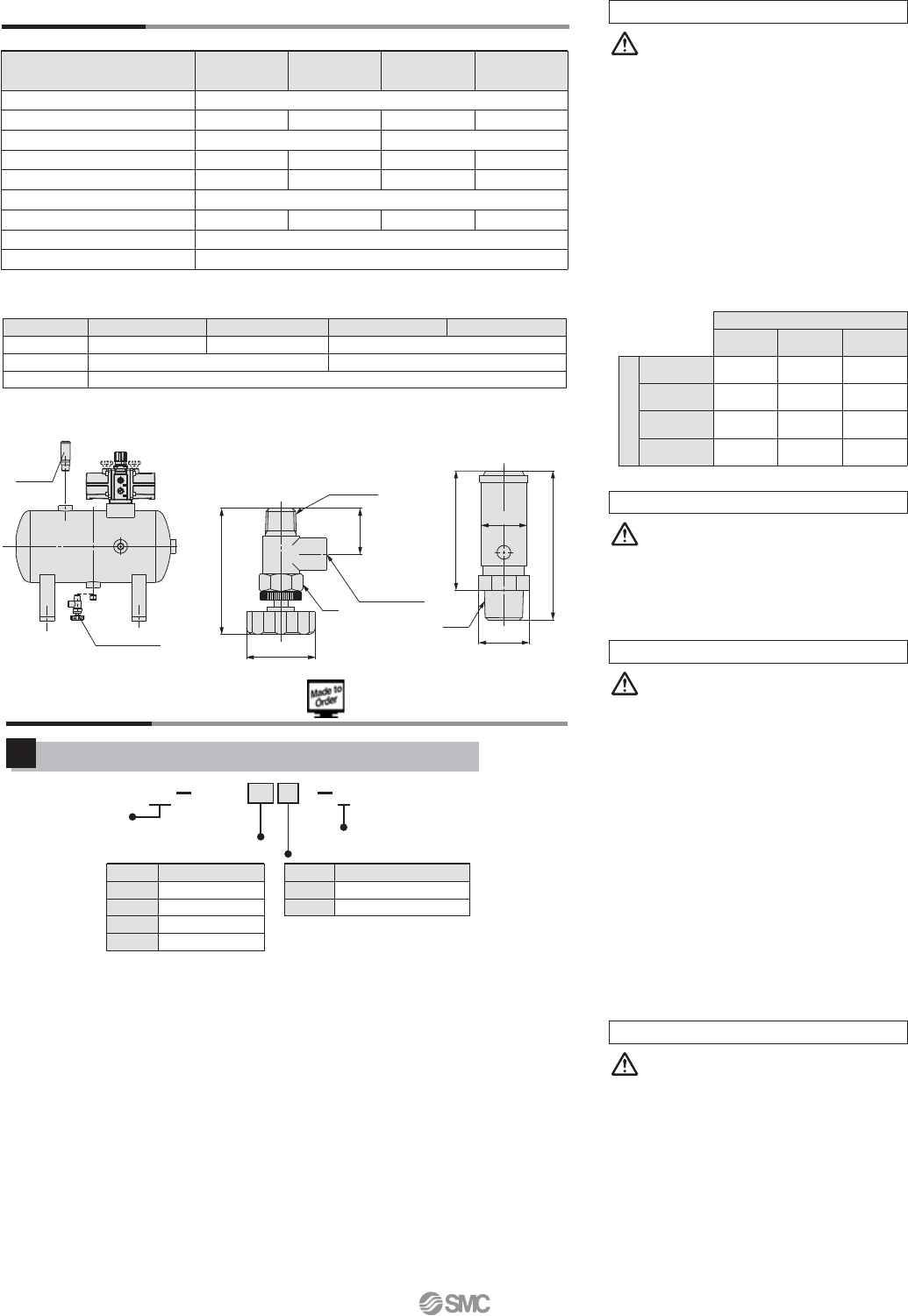
Air tank
Drain valve
IN PORT
1/4
19
OUT PORT
1/8
20
ø30
58 (CLOSE) to
63 (OPEN)
52
65
3/8
19
ø18.5
Safety
valve
Safety valve
VBAT-R, VBAT-S∗
Drain valve VBAT-V1∗
Copper-free/Fluorine-free
1
Note 1) The thread type for each port is Rc.
Note 2) A stainless steel fitting and a drain valve are included in the
same container as accessories. (For detailed dimensions,
please contact SMC.) A safety valve cannot be selected.
Note 3) Since neither copper nor fluorine parts are used for the
tank, a standard model can be used when options (safety
valve and drain valve) are not necessary.
20 1VBAT V
Made to Order
Copper-free/
Fluorine-free
Made to Order
Material
Carbon steel (SS400)
Stainless steel 304
Material
With drain valve
Symbol
A
S
Internal capacity
5 L
10 L
20 L
38 L
Tank internal
capacity
Symbol
05
10
20
38
A10
For detailed dimensions, specifications
and lead times, please contact SMC.
Model
VBAT05A쏔-SV-Q
VBAT10A쏔-SV-Q VBAT20A쏔-RV-Q VBAT38A쏔-RV-Q
Accessory kit
Safety valve
Drain valve
VBAT5A-Y-2
VBAT-S (Set pressure: 2 MPa)
VBAT-V1
VBAT10A-Y-2 VBAT20A-Y-2
VBAT-R (Set pressure: 1 MPa)
Series VBAT
13