
Datasheet


1.6
1.4
1.2
1
0.8
0.6
0.4
0.2
Outlet pressure (MPa)
0 500 1000 1500 2000 2500 3000
Outlet air flow rate (L/min (ANR))
1.08
1.06
1.04
1.02
1.0
0.98
0.96
0.94
Outlet pressure (MPa)
0 0.4 0.5 0.6 0.7 0.8 0.9 1
Inlet pressure (MPa)
0.1
0.08
0.06
0.04
0.02
Max. pulsation range (MPa)
012345
Capacity (L)
0.1
0.08
0.06
0.04
0.02
Max. pulsation range (MPa)
01020304038
Capacity (L)
5
4
3
2
1
0
Charge time per 10 L t (s)
1.0 1.1 1.2 1.3 1.4 1.5 1.6 1.7 1.8 1.9 2.0
Pressure increase ratio P2/P1
400
300
200
100
0
Charge time per 10 L t (s)
1.0 2.0 3.0 4.0
Pressure increase ratio P2/P1
Outlet pressure (MPa)
0 0.4 0.5 0.6 0.7 0.8 0.9 1
Inlet pressure (MPa)
2
1
Outlet pressure (MPa)
0 100 15050
Outlet air flow rate (L/min (ANR))
2.1
2.05
2.0
1.95
1.9
1.85
1.8
Pulsation/Pulsation is decreased with a tank.
If the outlet capacity is undersized, pulsation may
occur.
Conditions:
Inlet pressure: 0.5 MPa
Outlet set pressure: 1 MPa
Flow rate: Between 0 and max. flow rate
VBA2쏔A
VBA4쏔A
VBAT
VBA1쏔A
•
Performance of air tank
• Alleviates the pulsation generated on the
outlet side.
• When air consumption exceeds air supply
during intermittent operation, required air
will be accumulated in the tank for use.
This does not apply for continuous
operation.
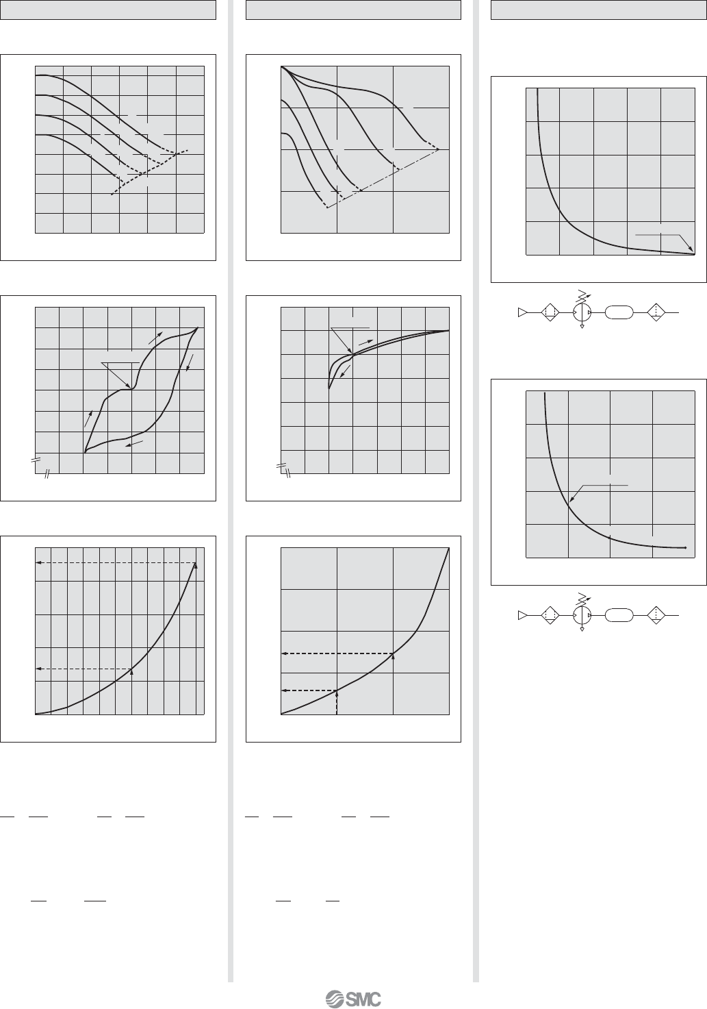
Flow-rate Characteristics
Charge Characteristics
Pressure
Characteristics
P
1
= 0.8 M
P
a
P
1
= 0.7 M
Pa
P
1
= 0.6 M
Pa
P
1
=
0.5 M
Pa
P1 = P2
VBAT05A
VBA43A
VBA43A
VBAT05A
VBAT10A, 20A, 38A
VBAT10A
VBAT20A
VBAT38A
VBAT
VBA11A
VBA11A
Flow-rate Characteristics
Charge Characteristics
Pressure
Characteristics
Set point
Set point
P
1
= 0.4 MPa
P
1
= 0.5 MPa
P
1
= 0.75 MPa
P
1
= 1.0 MPa
P1 = P2
P
1
= 0.3 M
P
a
Inlet pressure: 0.6 MPa
Outlet pressure: 2.0 MPa
Flow rate: 10 L/min (ANR)
Inlet pressure: 0.7 MPa
Outlet pressure: 1.0 MPa
Flow rate: 20 L/min (ANR)
쎲
The time required to charge pressure in the
tank from 0.8 MPa to 1.0 MPa at 0.5 MPa
supply pressure:
With the pressure increase ratio from 1.6 to 2.0,
the charge time of 4.5 – 1.3 = 3.2 sec. (t) is
given by the graph. Then, the charge time (T)
for a 100 L tank:
P
2
P1
0.8
0.5
= = 1.6 = 2.0
P
2
P1
1.0
0.5
=
T = t x = 3.2 x = 32 (s).
V
10
100
10
= 2.0 = 3.0
T = t x = 89 x = 89 (s).
V
10
10
10
쎲
The time required to charge pressure in the
tank from 1.0 MPa to 1.5 MPa at 0.5 MPa
supply pressure:
With the pressure increase ratio from 2.0 to 3.0,
the charge time of 147 – 58 = 89 sec. (t) is
given by the graph. Then, the charge time (T)
for a 10 L tank:
P
2
P1
1.0
0.5
=
P
2
P1
1.5
0.5
=
Booster Regulator Series VBA
(Representative
value)
(Representative
value)
4