
Datasheet


General line (low pressure) Locations requiring high pressure
VBA
VBA
VBA VBA
(Two-stage
pressure boost)
P2
P1
Shortening time
Without check
valve by-pass
Time t (S)
Outlet pressure (MPa)
P2
P1
0
Plant line (source pressure)
Operating pressure:
0.5 MPa
Bore size: ø100
Output ≈ 3850 N
Operating pressure:
0.8 MPa
Bore size: ø80
Output ≈ 4000 N
0.5 MPa
ø100
IN 0.5 MPa
E
ø80
OUT 0.8 MPa
Equivalent
output
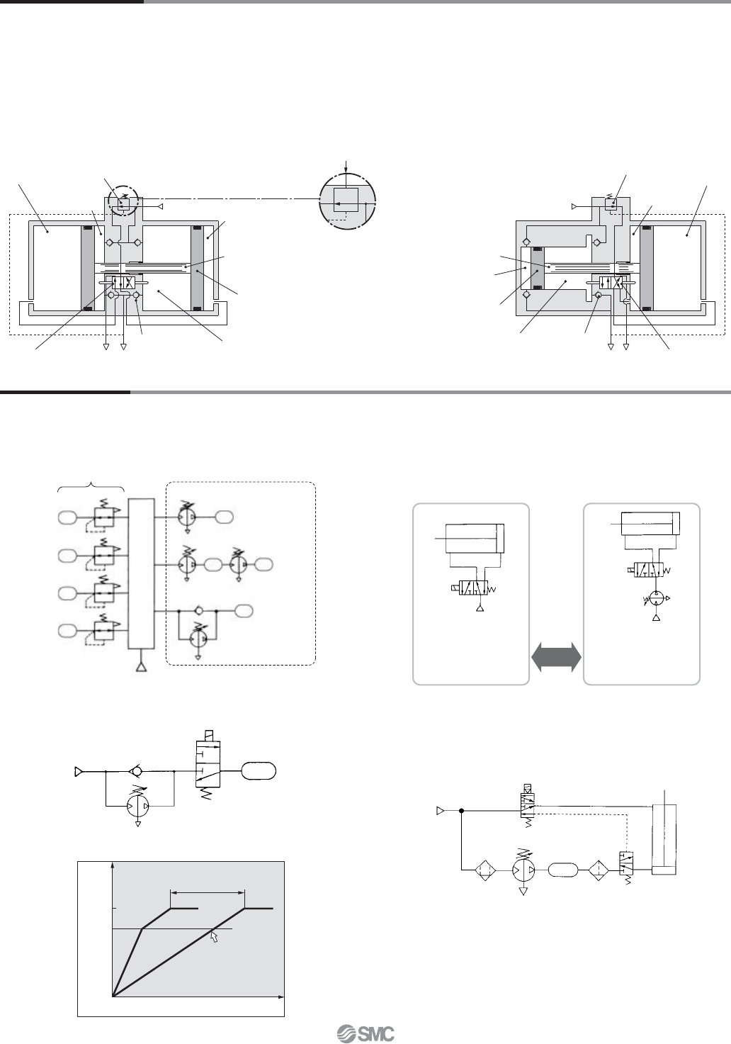
VBA22A, 42A
Air-operated type
Pilot pressure
IN (Inlet)
Governor
Booster
chamber A
Drive
chamber A
Switching valve
Piston
Drive chamber B
Booster chamber B
Check valve
OUT (Outlet)
E
Piston rod
Governor
Drive
chamber B
Drive
chamber A
Switching valve
EOUT (Outlet)
Check valveBooster
chamber B
Piston
Booster
chamber A
Piston rod
IN (Inlet)
Circuit Example
Working Principle
The IN air passes through the check valve to booster chambers A and B. Meanwhile, air is supplied to drive chamber B via the governor and
the switching valve. Then, the air pressure from drive chamber B and booster chamber A are applied to the piston, boosting the air in booster
chamber B. As the piston travels, the boosted air is pushed via the check valve to the OUT side. When the piston reaches to the end, the piston
causes the switching valve to switch, so that drive chamber B is in the exhaust state and drive chamber A is in the supply state respectively.
Then, the piston reverses its movement, this time, the pressures from booster chamber B and drive chamber A boosts the air in booster
chamber A and sends it to the OUT side. The process described above is repeated to continuously supply highly pressurized air from the IN to
the OUT side. The governor establishes the outlet pressure by handle operation and pressure adjustment in the drive chamber by feeding back
the outlet pressure.
VBA10A, 20A, 40A, 43A
Initially, inlet pressure (P1) passes through the check valve, fills P2,
and results in P1 = P2.
VBA11A
• When only some of the machines in the plant require high-pressure
air, booster regulators can be installed for only the equipment that
requires it. This allows the overall system to use low-pressure air
while accommodating machines requiring high-pressure air.
• When the actuator output is insufficient but space limitations prohibit
switching to a larger cylinder diameter, a booster regulator can be
used to increase the pressure. This makes it possible to boost the
output without replacing the actuator.
• When a certain level of output is required but the cylinder size must
be kept small so that the driver remains compact.
• When charging a tank or the like from a source at atmospheric
pressure, a circuit with a check valve can be used to reduce the
charge time by allowing air to pass through the check valve up to
the inlet pressure.
• When only one side of the cylinder is used for work, booster
regulators can be installed only on the lines that require them to
reduce the overall air consumption volume.
Booster Regulator Series VBA
6