
Datasheet


Piping adapter
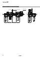
Pressure switch with
piping adapter
0.2
0.4
0.1
0.3
MPa
Port
size
Centre of F.R.L. body
D A
B
C
(23)
(13)
23 E
(5000)
(3000)
(500)
Symbol Description
Vq
Body size
20 30 40
Vw
Pipe thread type
—
Rc
N
Note)
NPT
F
Note)
G
+
Ve
Port size
01
1/8
— —
02
1/4
03
3/8
04
1/2
—
06
3/4
— —
+
Vr
Semi-standard
a
Set pressure
range
—
0.1 to 0.4 MPa
6
Note 1)
0.1 to 0.6 MPa
+
b
Lead wire
length
—
0.5 m
L
3 m
Z
5 m
+
c
Pressure unit of
the scale plate
—
MPa
P
Note 2)
MPa/psi dual scale
+
d
Mounting
position
—
Right
R
Left
Model
Note 1)
Port size
A B C D E
Applicable model
IS10E-20l01-A
1/8
29.8 66.3 55.3 28 16
AC20l-BIS10E-20l02-A
1/4
IS10E-20l03-A
3/8
IS10E-30l02-A
1/4
31.8 72.8 58.8 30 13
AC25l-B,
AC30l-B
IS10E-30l03-A
3/8
IS10E-30l04-A
1/2
IS10E-40l02-A
1/4
31.8 78.8 60.8 37 12.5
Note 2)
AC40l-B
IS10E-40l03-A
3/8
IS10E-40l04-A
1/2
IS10E-40l06-A
3/4
Model
Note)
Port size
A B D
Applicable model
E100-M5-A
M5 x 0.8 10 14 14
AC10l-A
E200-
l01-A
1/8
29.8 23.5 28
AC20l-BE200-l02-A
1/4
E200-l03-A
3/8
E300-l02-A
1/4
31.8 30 30
AC25l-B, AC30l-BE300-l03-A
3/8
E300-l04-A
1/2
E400-l02-A
1/4
31.8 36 36
AC40l-B
E400-
l03-A
3/8
E400-l04-A
1/2
E400-l06-A
3/4
E500-l06-A
3/4 31.8 40 44
AC40l-06-B
E600-
l06-A
3/4
35 48 53
AC50-B, AC55-B, AC60-B,
AC50A-B, AC60A-B, AC50B-B,
AC55B-B, AC60B-B
E600-l10-A
1
Contact point confi guration 1a
Maximum contact point capacity
2 VA (AC), 2 W (DC)
Operating voltage: AC, DC 100 V or less
Maximum operating current
12 V to 24 V AC, DC: 50 mA
48 V AC, DC: 40 mA
100 V AC, DC: 20 mA
Fluid Air
Ambient and fl uid temperature
−5 to 60°C (with no freezing)
Proof pressure 1.0 MPa
Maximum operating pressure
0.7 MPa
Set pressure range (when OFF)
0.1 to 0.4 MPa
Hysteresis 0.08 MPa or less
A piping adapter allows installation/removal of the component
without removing the piping and thus makes maintenance easier.
Note) l in model numbers indicates a pipe thread type. No indication is
necessary for Rc; however, indicate N for NPT, and F for G.
∗ Separate interfaces are required for modular unit.
∗ Factory mounting of a piping adapter on the AC models is available as a
special order.
Specifi cations
Switch Characteristics
Piping Adapter: M5 x 0.8, 1/8, 1/4, 3/8, 1/2, 3/4, 1
Symbol
IS10E A
30
q
03
rw e
Pressure Switch with Piping Adapter
• Semi-standard: Select one each for a to d.
•
Semi-standard symbol: When more than one specifi cation is required, indicate in alphanumeric order.
Example) IS10E-30N03-6PRZ
Note 1) Set pressure range of 6P (L, R, Z) is 0.2 to 0.6 MPa (30 to 90 psi).
Note 2)
For pipe thread type: NPT only.
Note 1) l in the model numbers indicates a pipe thread type. No indication is
necessary for Rc; however, indicate N for NPT, and F for G.
Note 2) Cannot be mounted on the AC40l-06-B.
∗ Separate interfaces are required for modular unit.
∗ The pressure switch on the AC40l-06-B can be mounted by screwing IS10-
01S into the piping adapter E500-l06-A-X501 (with top-face thread Rc1/8).
Products with a premounted switch are available as a special order. Please
contact SMC regarding their availability.
B
D
A
Centre of
F.R.L.
body
Port size
Left Right
37
Series AC