Contents 1. INSTRUCTIONS FOR SAFE AND PROPER USE_______________ 37 2. INSTALLATION OF THE APPLIANCE________________________ 39 3. ADAPTATION TO DIFFERENT TYPES OF GAS _______________ 42 4. FINAL OPERATIONS _____________________________________ 43 5. DESCRIPTION OF CONTROLS ____________________________ 45 6. USE OF THE COOKING HOB ______________________________ 50 7. USE OF THE OVENS_____________________________________ 51 8. AVAILABLE ACCESSORIES _______________________________ 52 9.
Introduction 1. INSTRUCTIONS FOR SAFE AND PROPER USE THIS MANUAL IS AN INTEGRAL PART OF THE APPLIANCE AND THEREFORE MUST BE KEPT IN ITS ENTIRETY AND IN AN ACCESSIBLE PLACE FOR THE WHOLE WORKING LIFE OF THE COOKER. WE ADVISE READING THIS MANUAL AND ALL THE INSTRUCTIONS THEREIN BEFORE USING THE COOKER. ALSO KEEP THE SERIES OF NOZZLES SUPPLIED. INSTALLATION MUST BE CARRIED OUT BY QUALIFIED PERSONNEL IN ACCORDANCE WITH THE REGULATIONS IN FORCE.
Introduction THE I.D. PLATE WITH TECHNICAL DATA, REGISTRATION NUMBER AND BRAND NAME IS POSITIONED VISIBLY IN THE STORAGE COMPARTMENT. THE PLATE MUST NOT BE REMOVED. DO NOT INSTALL THIS APPLIANCE ON A RAISED PLATFORM. DURING USE THE APPLIANCE BECOMES VERY HOT. TAKE CARE NOT TO TOUCH THE HEATING ELEMENTS INSIDE THE OVEN. DO NOT PUT PANS WITHOUT PERFECTLY SMOOTH AND FLAT BOTTOMS ON THE COOKING HOB GRIDS. DO NOT USE CONTAINERS OR BROILERS THAT EXTEND BEYOND THE OUTER PERIMETER OF THE HOB.
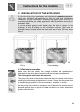
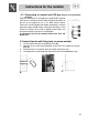
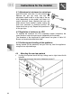
Instructions for the installer 2. INSTALLATION OF THE APPLIANCE It is the law that all gas appliances are installed by competent persons. Corgi gas installers are approved to work to safe and satisfactory standards. All gas installation, servicing and repair work must be in accordance with the gas safety regulations 1984 (installation and use) as amended 1990. It can be placed against walls higher than the hob as shown in the drawings A and B relating to the installation classes.
Instructions for the installer For operation on 380-415V3N∼: use an 2 H05RR-F-type five-core cable (5 x 1.5 mm ). For operation on 380-415V2N∼: use an H05RR-F-type four-core cable (4 x 1.5 mm2). For operation on 220-240V∼: use an H05RR-F-type three-core cable (3 x 2.5 mm2). The cable end to be connected to the appliance must be provided with an ground wire (yellow-green) at least 20 mm longer.
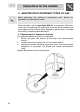
Instructions for the installer 2.3 Connecting to natural and LPG gas (Please see connection diagram) Make the connection to the appliance using flexible bayonet style hose in accordance to B.S. 669. The hose connection at the rear of the appliance has a 1/2" BSP internal thread. Please use seal C between the flexible connection L and the appliance supply tube B. When making the connection, make sure that no stress of any kind is applied to the cooker and that the hose does not touch any sharp edges.
Instructions for the installer 3. ADAPTATION TO DIFFERENT TYPES OF GAS Before performing any cleaning or maintenance work, detach the appliance from the electrical socket. The cooker hob is set for natural gas G20 (2H) at a pressure of 20 mbar. In the case of functioning with other types of gas the burner nozzles must be changed and the minimum flame adjusted on the gas taps. To change the nozzles, proceed as described below. 3.
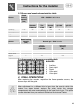
Instructions for the installer 3.2 Burner and nozzle characteristics table Burner Auxiliary Semi rapid Rapid Triple crown Burner Auxiliary Semi rapid Rapid Triple crown Rated heating capacity (kW) LPG – G30/G31 28/37 mbar Nozzle diameter 1/100 mm By-pass mm 1/100 Reduced flowrate (W) 1.05 50 30 360 76 75 1.8 65 33 450 131 129 3 85 45 750 218 215 3.
Instructions for the installer 4.1 Adjustment of minimum for natural gas Light the burner and take it to the minimum . Remove the gas tap knob and turn the adjustment screw inside or at the side of the tap shaft (depending on the model) until there is a regular minimum flame. Replace the knob and check burner flame stability: (rapidly turning the knob from maximum to minimum position, the flame should not go out). Repeat the operation on all the gas taps. 4.
Instructions for the user 5. DESCRIPTION OF CONTROLS 5.1 Front control panel All the cooker controls and commands are on the front panel. The user has only to press the central key for 1 - 2 seconds to enable use of the oven on first use or after a power blackout.
Instructions for the user THERMOSTAT KNOB (OVENS) Selection of cooking temperature is carried out by turning the knob clockwise to the required temperature, between 50° and 250°C. The tell-tale light comes on to indicate that the oven is warming up. When it goes out it means that the required temperature has been reached. Regular flashing means that oven temperature is being constantly maintained at the programmed level.
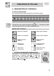
Instructions for the user 5.2 Electronic Analogue Clock LIST OF FUNCTIONS MINUTE-MINDER BUTTON AUTOMATIC SWITCH-OFF TIMING BUTTON TIME SETTING AND RESET VALUE DECREASE BUTTON VALUE INCREASE BUTTON 5.2.1 Setting the time When the oven is used for the first time, or after a power blackout, the display flashes on and off at regular intervals. Press the key for 1/2 seconds to stop the display flashing and start setting of the current time.
Instructions for the user 5.2.2 Minute-minder This function does not stop cooking but just triggers the beeps. - When the key is pressed the display illuminates, appearing as shown in figure 1; - Press the or keys within 6/7 seconds to set the minute-minder. Whenever a key is pressed, 1 outside segment, representing 1 cooking minute will light up (figure 2 shows 10 cooking minutes). The countdown will start 6/7 seconds after the last key is pressed; at the end of it, you will hear the beeps.
Instructions for the user - When the end of the cooking time is reached, the timer will switch off the oven heating elements, the beeps will start and the numbers on the dial will flash. The cooking time can also be reset by deleting the program set; for 1 or 2 seconds will delete the time set pressing the central key and the oven will have to be switched off by hand. Caution: cooking times of more than 6 hours cannot be set.
Instructions for the user 6. USE OF THE COOKING HOB 6.1 Lighting of the cooking hob burners Before lighting the hob burners check that the flame caps are in the correct position and that their burner caps are in place, making sure that the holes A in the flame caps correspond to the spark plugs and thermocouples. Grid B should be used with Chinese woks. Each knob corresponds to the burner indicated. The appliance is equipped with an electronic lighting device.
Instructions for the user 7. USE OF THE OVENS 7.1 Warnings and general advice Before using the oven for the first time, pre-heat it to maximum temperature (250°C) long enough to burn any manufacturing oily residues which could give the food a bad taste. for 1 - 2 seconds to enable The user has only to press the central key use of the oven on first use or after a power blackout. To regulate, refer to paragraph "5.2 Electronic Analogue Clock”.
Instructions for the user 7.4 Storage compartment The storage drawer is at the bottom of the cooker, underneath the oven. For access, pull the bottom of the door. Never store inflammable materials such as rags, paper or the like. The compartment is intended only for holding the metal accessories of the range. Never open the storage compartment when the oven is on and still hot. The temperature inside may be very high. 8.
Instructions for the user 9. COOKING HINTS In fan-assisted mode preheating should be carried out at 30/40°C above the cooking temperature. This considerably shortens cooking times and reduces power consumption, as well as giving better cooking results. Keep the oven door closed during cooking 9.
Instructions for the user 9.2 Hot-air cooking (main oven) FUNCTION SWITCH THERMOSTAT SELECTOR SWITCH FROM 50° TO 250°C This system is suitable for cooking on several levels, including different types of food (fish, meat etc.), without the tastes and smells mingling. Air circulation in the oven ensures a uniform distribution of heat. Pre-heating is not necessary. Multiple cooking is possible as long as the cooking temperature of the different foods is the same. 9.
Instructions for the user 9.4 Hot-air grilling (main oven) FUNCTION SWITCH THERMOSTAT SWITCH FROM 50° TO 200°C Ensures uniform heat distribution with greater heat penetration into the food. Food will be lightly browned on the outside and remain soft inside. Keep the oven door closed during cooking. Heating up time must not exceed 60 minutes. Keep the oven door closed during grilling. Grilling with the door open could permanently damage the oven and affect safety of operation. 9.
Instructions for the user 9.6 Defrosting (main oven) FUNCTION SWITCH THERMOSTAT SWITCH IN POSITION 0 The flow of air produced by the fan ensures quicker defrosting. The air circulating inside the oven is at room temperature. The advantage of defrosting at room temperature is that it does not alter the taste and appearance of the food.
Instructions for the user 9.7 Spit cooking (auxiliary oven) FUNCTION SWITCH THERMOSTAT SWITCH AT MAXIMUM This type of cooking is only for the auxiliary oven. Use it for small size pieces. Prepare the spit with the food, blocking fork screws A. Insert frame B into the third guide from the bottom. Remove handle D and position the spit shaft so that pulley E is guided on the link of frame B.
Instructions for the user 9.8 Recommended cooking table Cooking times, especially meat, vary according to the thickness and quality of the food and to consumer taste.
Instructions for the user TOAST 4 2-4 2-3 HOT-AIR COOKING FIRST COURSES LASAGNE OVEN-BAKED PASTA CREOLE RICE MEAT ROAST VEAL ROAST PORK ROASTED BEEF FILLET OF BEEF ROAST LAMB ROAST BEEF ROAST CHICKEN ROAST DUCK ROAST TURKEY ROAST RABBIT ROAST HARE ROAST PIGEON FISH PIZZA DESSERTS (PASTRIES) CIAMBELLA FRUIT CAKE SPONGE-CAKE BRIOCHES STRUDEL SAVOYARD PUDDING BREAD TOAST LEVEL FROM BELOW TEMPERATURE (°C) TIME IN MINUTES 2 2 2 190 - 210 190 - 210 190 - 220 20 - 25 25 - 30 20 - 25 2 2 2 2 2 2 2 2 2 2
Instructions for the user 10. CLEANING AND MAINTENANCE 10.1 Cleaning stainless steel Before performing any operations requiring access to powered parts, switch off the power supply to the machine. To keep stainless steel in good condition it should be cleaned regularly after use. Let it cool first. 10.1.1 Ordinary Daily Cleaning To clean and preserve the stainless steel surfaces, always use only specific products that do not contain abrasives or chlorine-based acids.
Instructions for the user 10.2.2 Burner caps, flame cap crowns and burners To facilitate cleaning, caps, flame cap crowns, and burners are all removable. To remove the flame separating crown of the fish hob, loosen the two screws exposed after having removed the cap. Wash all parts with warm water and non-abrasive detergent taking care to remove all tough spots. Wait for all parts to be fully dry before remounting.
Instructions for the user For easier cleaning, the storage drawer underneath the oven can be completely removed. Pull it right out and raise the front (as for an ordinary drawer). On some models, once the drawer has been pulled completely out the two tabs have to be pushed up as shown in the diagram, after which the drawer can be removed from the appliance. 10.3.1 Self-cleaning liners (main oven) The main oven is equipped with continuous self-cleaning enamelled liners.
Instructions for the user 10.3.4 1. 2. 3. 4. 5. Assembling the self-cleaning liners Remove all accessories from the oven; Remove the side grilles (fig.1); Extract the side liners “F” and “G”(fig. 2); Remove the back panel “A” after undoing the threaded ring-nut “C” (fig. 2). Reassemble the panels, restoring them to their original position. 1) 2) 10.4 Door glass These should always be kept very clean.
Instructions for the user 11.EXTRAORDINARY MAINTENANCE Ovens periodically require small maintenance interventions or replacement of parts subject to wear and tear such as gaskets, electric bulbs etc. Specific instructions for each intervention of this type appear below. Before performing any operations requiring access to powered parts, switch off the power supply to the machine. 11.1 Replacement of light bulbs Remove cover A by twisting anticlockwise, replace bulb B with another similar bulb.
Instructions for the user 11.2 Removing the door Open the door completely and fit the pins (supplied) into the holes from the inside. Close the door to an angle of about 45°, lift it and remove it from its seat. To replace, fit the hinges into the grooves provided, then lower the door until it comes to rest and extract the pins. If the pins are lost, two screwdrivers can also be used. 11.3 Oven door gaskets The door gaskets can be dismantled for thorough cleaning of the ovens.