Contents 1. INSTRUCTIONS FOR SAFE AND PROPER USE _______________40 2. INSTALLATION OF THE APPLIANCE ________________________42 3. ADAPTATION TO DIFFERENT TYPES OF GAS ________________45 4. FINAL OPERATIONS______________________________________47 5. DESCRIPTION OF CONTROLS _____________________________49 6. USE OF THE COOKING HOB _______________________________55 7. USE OF THE OVENS _____________________________________57 8. ACCESSORIES __________________________________________58 9.
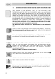
Introduction 1. INSTRUCTIONS FOR SAFE AND PROPER USE THIS MANUAL IS AN INTEGRAL PART OF THE APPLIANCE AND THEREFORE MUST BE KEPT IN ITS ENTIRETY AND IN AN ACCESSIBLE PLACE FOR THE WHOLE WORKING LIFE OF THE COOKER. WE ADVISE READING THIS MANUAL AND ALL THE INSTRUCTIONS THEREIN BEFORE USING THE COOKER. ALSO KEEP THE SERIES OF NOZZLES SUPPLIED. INSTALLATION MUST BE CARRIED OUT BY QUALIFIED PERSONNEL IN ACCORDANCE WITH THE REGULATIONS IN FORCE.
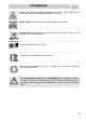
Introduction DURING USE THE APPLIANCE BECOMES VERY HOT. TAKE CARE NOT TO TOUCH THE HEATING ELEMENTS INSIDE THE OVEN. DO NOT INSTALL THIS APPLIANCE ON A RAISED PLATFORM DO NOT PUT PANS WITHOUT PERFECTLY SMOOTH AND FLAT BOTTOMS ON THE COOKING HOB GRIDS. DO NOT USE CONTAINERS OR BROILERS THAT EXTEND BEYOND THE OUTER PERIMETER OF THE HOB. THE APPLIANCE IS DESIGNED FOR USE BY ADULTS. DO NOT ALLOW CHILDREN TO GO NEAR OR PLAY WITH IT. REPLACED APPLIANCES MUST BE TAKEN TO A SPECIAL GARBAGE COLLECTION CENTRE.
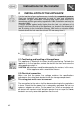
Instructions for the installer 2. INSTALLATION OF THE APPLIANCE It is the law that all gas appliances are installed by competent persons. Corgi gas installers are approved to work to safe and satisfactory standards. All gas installation, servicing and repair work must be in accordance with the gas safety regulations 1984 (installation and use) as amended 1990.
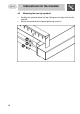
Instructions for the installer The connection terminals are located at the rear of the appliance. For electrical connections see following diagram. To access, remove the rear cover. For operation on 400-415V3N∼: use an H05RR-F-type five-core cable (5 x 2 1.5 mm ). For operation on 400-415V2N∼: use an H05RR-F-type four-core cable (4 x 2 2.5 mm ). For operation on 230-240V∼: use an H05RR-F-type three-core cable (3 x 4 2 mm ).
Instructions for the installer 2.3 Ventilation requirements The room containing the appliance should have an air supply in accordance with B.S. 5440 part 2 1989. 1. All rooms require an opening window or equivalent, and some rooms will require a permanent vent as well. 3 2 2. For room volumes up to 5 m an air vent of 100 cm is required. 3. If the room has a door that opens directly to the outside, and the 3 room exceeds 1 m no air vent is required. 3 3 2 4.
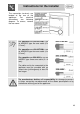
Instructions for the installer 3. ADAPTATION TO DIFFERENT TYPES OF GAS Before performing any cleaning or maintenance work, switch off the power supply to the appliance. The cooking hob of the cooker is preset for G20 natural gas at a pressure of 20 mbar. In the case of functioning with other types of gas the burner nozzles must be changed and the minimum flame adjusted on the gas taps. Replace the burner nozzles as indicated in the table of the gas to be used. 3.1 Changing nozzles 1. 2. 3.
Instructions for the installer 3.2 Burner and nozzle characteristics table Burner Auxiliary Semi rapid Rapid Fish Burner Triple crown Burner Rated heating capacity (kW) 1.05 1.8 3.0 1.9 3.3 LPG – G30/G31 28/37 mbar (drawing ref. X238) Nozzle diameter 1/100 mm By-pass Mm 1/100 Reduced flowrate (W) Flowrate g/h G30 Flowrate g/h G31 50 65 85 68 91 30 33 45 45 68 360 450 750 800 1600 76 131 218 138 218 75 129 215 136 215 Rated heating capacity (kW) NATURAL GAS – G20 20 mbar Auxiliary 1.
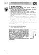
Instructions for the installer 4. FINAL OPERATIONS After replacing the nozzles, reposition the flame-spreader crowns, the burner caps and the grids. Following adjustment to a gas other than the preset one, replace the gas adjustment label fixed to the appliance with the one corresponding to the new gas. This label is in the packet together with the nozzles. 4.1 Adjustment of minimum for natural gas Light the burner and turn it to the minimum position .
Instructions for the installer 4.3 • • 48 Mounting the rear top upstand Position the upstand above the top, taking care to align holes A with holes B. Secure the upstand to the top by tightening screws C.
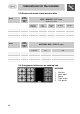
Instructions for the user 5. DESCRIPTION OF CONTROLS 5.1 Front control panel All the cooker controls and commands are on the front panel. Before using the main oven check that the electronic programmer is showing the symbol (see paragraph “5.2.1 Clock adjustment”).
Instructions for the user MAIN OVEN THERMOSTAT KNOB Selection of cooking temperature is carried out by turning the knob clockwise to the required temperature, between 50° and 250°C. The tell-tale light comes on to indicate that the oven is warming up. When it goes out it means that the required temperature has been reached. Intermittent going on and off of the light means that the oven temperature is being constantly maintained at the programmed level.
Instructions for the user MAIN OVEN FUNCTION SWITCH KNOB Turn the knob to select from the following functions: NO FUNCTION SET OVEN LIGHT GRILL ELEMENT + VENTILATION UPPER AND LOWER HEATING ELEMENT LOWER HEATING ELEMENT + VENTILATED HEATING ELEMENT VENTILATED HEATING ELEMENT + VENTILATION GRILL ELEMENT AUXILIARY OVEN THERMOSTAT KNOB Selection of cooking temperature is carried out by turning the knob clockwise to the required temperature, between 50° and 220°C.
Instructions for the user 5.2 Electronic Programmer The programmer user instructions are valid only for the main oven. LIST OF FUNCTIONS MINUTE-COUNTER KEY COOKING TIME KEY END-OF-COOKING KEY DECREASE TIME KEY INCREASE TIME KEY 5.2.1 Clock adjustment When using the oven for the first time, or after a power failure, the display flashes regularly and indicates . Press the keys and at o : each single press changes the time by 1 the same time the keys minute either up or down.
Instructions for the user 5.2.2 Semiautomatic cooking Use this setting for automatic oven switch-off at the end of cooking time. , the display lights up, showing ; keep the key By pressing key pressed and at the same time, press keys o to set the cooking time. Release key to start the programmed cooking time count. The display will now show the right time together with symbols A and . 5.2.3 Automatic cooking Use this setting to automatically start and stop the oven.
Instructions for the user 5.2.5 Adjusting alarm volume The acoustic alarm has three different settings. These can be operated, . while the alarm is sounding, by pressing key 5.2.6 Switching off the alarm The alarm switches off automatically after seven minutes. They can be manually de-activated by pressing the keys and together. 5.2.7 Minute Counter The programmer can also be used as a simple minute counter. By pressing key , the display shows ; keep the key pressed and at the same time press keys o .
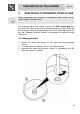
Instructions for the user 6. USE OF THE COOKING HOB 6.1 Lighting of the cooking hob burners Before lighting the cooking hob burners check that the flame cap crowns are properly positioned with their appropriate burner caps: niche A must be centred with pin B. Grid C should be used with Chinese woks. Each knob corresponds to the burner indicated. The appliance is equipped with an electronic lighting device. Just press and turn the knob until the burner lights.
Instructions for the user 6.2 Practical advice for using the cooking hob burners For better use of the burners and lower gas consumption, use covered containers that are proportional in size to the burner to prevent the flame from licking the sides (see paragraph “0 Diameter of containers”). When water reaches the boiling point, lower the flame so that it doesn’t overflow. To avoid burns or damage to the hob, all recipients or griddle plates must be placed within the perimeter of the cooking hob.
Instructions for the user 7. USE OF THE OVENS 7.1 Warnings and general advice Before using the oven for the first time, pre-heat it to maximum temperature (250°C) long enough to burn any manufacturing oily residues which could give the food a bad taste. After a power failure, the display will flash at regular intervals showing . To regulate, refer to paragraph “5.2 Electronic Programmer”.
Instructions for the user 8. ACCESSORIES The oven features 4 support positions for plates and racks of different height. Oven grill: for cooking food on plates, small cakes, roasts or food requiring light grilling. Plate grill: for placing above plate for cooking foods that might drip. Oven plate: useful for catching fat from foods on the grill above. Pastry plate: for baking cakes, pizza and oven desserts.
Instructions for the user Accessories on Request You can order the lower base and self-cleaning oven panels through Authorised Assistance Centres. Two optional accessories are also available from Authorised Service Centres: Griddle plate on gas burner: this optional plate is for installation on the hob instead of the right-hand pan stand (fish burner). Take care that the feet of the griddle plate are resting firmly on the base of the hob to prevent the risk of tipping.
Instructions for the user 9. COOKING HINTS In fan-assisted mode preheating should be carried out at 30/40°C above the cooking temperature. This considerably shortens cooking times and reduces power consumption, as well as giving better cooking results. Keep the oven door closed during cooking 9.
Instructions for the user 9.2 Hot-air cooking (main oven) FUNCTION SWITCH THERMOSTAT SELECTOR SWITCH FROM 50° TO 250°C This system is suitable for cooking on several levels, including different types of food (fish, meat etc.), without the tastes and smells mingling. Air circulation in the oven ensures a uniform distribution of heat. Pre-heating is not necessary. Multiple cooking is possible as long as the cooking temperature of the different foods is the same. 9.
Instructions for the user 9.4 Hot-air grilling (main oven) FUNCTION SWITCH THERMOSTAT SWITCH FROM 50° TO 200°C Ensures uniform heat distribution with greater heat penetration into the food. Food will be lightly browned on the outside and remain soft inside. Keep the oven door closed during cooking. Heating up time must not exceed 60 minutes. 9.5 Variable grill cooking (auxiliary oven) THERMOSTAT SWITCH IN POSITION VARIABLE GRILL CHOICE BETWEEN MIN. AND MAX.
Instructions for the user 9.6 Delicate cooking (auxiliary oven) FUNCTION SWITCH THERMOSTAT SWITCH AT MAXIMUM Ideal for pastries and cakes with wet covering and little sugar and damp desserts in moulds. Excellent results can also be achieved in completing cooking at the bottom and with dishes requiring heat in the lower area in particular. The plate is best inserted at bottom level. 9.
Instructions for the user 9.8 Spit cooking (main oven) FUNCTION SWITCH THERMOSTAT SWITCH FROM 50° TO 200°C Prepare the spit with the food, blocking fork screws A. Insert frame B into the third guide from the bottom. Remove handle D and position the spit shaft so that pulley E is guided on the link of frame B in the right side. Insert the drip tray into the oven as far as it will go until the tip of the rod is in line with the hole C.
Instructions for the user 9.9 Spit cooking (auxiliary oven) FUNCTION SWITCH VARIABLE GRILL CHOICE BETWEEN MIN. AND ¾ MAX Use it for small size pieces. Prepare the spit with the food, blocking fork screws A. Insert frame B into the third guide from the bottom. Remove handle D and position the spit shaft so that pulley E is guided on the link of frame B. Fully insert frame B until the point of the spit shaft enters the spit-turning motor housing C on the rear wall of the oven.
Instructions for the user 9.10 Recommended cooking table Cooking times, especially meat, vary according to the thickness and quality of the food and to consumer taste.
Instructions for the user HOT-AIR COOKING FIRST COURSES LASAGNE OVEN-BAKED PASTA CREOLE RICE MEAT ROAST VEAL ROAST PORK ROASTED BEEF FILLET OF BEEF ROAST LAMB ROAST BEEF ROAST CHICKEN ROAST DUCK ROAST TURKEY ROAST RABBIT ROAST HARE ROAST PIGEON FISH PIZZA DESSERTS (PASTRIES) CIAMBELLA FRUIT CAKE SPONGE-CAKE BRIOCHES STRUDEL SAVOYARD PUDDING BREAD TOAST LEVEL FROM BELOW TEMPERATURE (°C) TIME IN MINUTES 2 2 2 190 - 210 190 - 210 190 - 220 20 - 25 25 - 30 20 - 25 2 2 2 2 2 2 2 2 2 2 2 2 2-3 150 - 170
Instructions for the user 10. CLEANING AND MAINTENANCE 10.1 Cleaning stainless steel To keep stainless steel in good condition it should be cleaned regularly after use. Let it cool first. 10.1.1 Ordinary Daily Cleaning To clean and preserve the stainless steel surfaces, always use only specific products that do not contain abrasives or chlorine-based acids. How to use: pour the product on a damp cloth and wipe the surface, rinse thoroughly and dry with a soft cloth or deerskin. 10.1.
Instructions for the user 10.2.2 Barbecue drip tray To remove the drip tray under the barbecue element: 1. Remove the griddle as described in point 10.2.1; 2. Raise the heating element and fix it in place by sliding the retainer to the right (as shown in the adjacent diagram); 3. Remove the drip tray using the two handles and clean using specific detergents for stainless steel and a non-abrasive sponge. 10.2.3 Grids Remove the right-hand pan stands (griddle + fish burner) as shown in the diagram.
Instructions for the user 10.2.5 Ignition plugs and thermocouples To work well, the ignition plugs and thermocouples must always be very clean. Check them frequently and clean them with a wet rag if necessary. Any dry residue should be removed with a toothpick or a needle. 10.3 Cleaning of ovens (without self-cleaning panels) To keep an oven in good condition it must be cleaned regularly. Let it cool first. Take out all the removable parts.
Instructions for the user 10.3.2 Using the self-cleaning liners Periodically, to prevent food residues and unpleasant smells from accumulating inside the oven, the appliance should be operated empty at temperatures of not less than 200°C for a time varying from 30 to 60 minutes, in order to allow the self-cleaning liners to oxidise the residues present; when the oven has cooled, these will then be removed with a damp sponge 10.3.
Instructions for the user 11. EXTRAORDINARY MAINTENANCE Ovens periodically require small maintenance interventions or replacement of parts subject to wear and tear such as gaskets, electric bulbs etc. Specific instructions for each intervention of this type appear below. Before performing any operations requiring access to powered parts, switch off the power supply to the machine. 11.1 Replacement of light bulbs Remove cover A by twisting anticlockwise, replace bulb B with another similar bulb.
Instructions for the user 11.2 Dismantling of the doors Hold the door on both sides with both hands near hinges A and raise levers B. Lift up the door forming an angle of about 45° and remove. To refit, slide the hinges A in the grooves, drop the door and release levers B. 11.3 Oven door gaskets The door gaskets can be dismantled for thorough cleaning of the ovens. Before removing the gaskets the oven doors must be removed as previously described.