Contents 1. INSTRUCTIONS FOR SAFE AND PROPER USE _____________________ 36 2. INSTALLATION OF THE APPLIANCE ______________________________ 38 3. ADAPTATION TO DIFFERENT TYPES OF GAS ______________________ 42 4. FINAL OPERATIONS ___________________________________________ 44 5. DESCRIPTION OF CONTROLS___________________________________ 45 6. USE OF THE COOKING HOB ____________________________________ 52 7. USE OF THE OVENS ___________________________________________ 53 8.
Introduction 1. INSTRUCTIONS FOR SAFE AND PROPER USE THIS MANUAL IS AN INTEGRAL PART OF THE APPLIANCE AND THEREFORE MUST BE KEPT IN ITS ENTIRETY AND IN AN ACCESSIBLE PLACE FOR THE WHOLE WORKING LIFE OF THE COOKER. WE ADVISE READING THIS MANUAL AND ALL THE INSTRUCTIONS THEREIN BEFORE USING THE COOKER. ALSO KEEP THE SERIES OF NOZZLES SUPPLIED. INSTALLATION MUST BE CARRIED OUT BY QUALIFIED PERSONNEL IN ACCORDANCE WITH THE REGULATIONS IN FORCE.
Introduction NEVER PUT INFLAMMABLE OBJECTS INTO AN OVEN: IF THEY CATCH FIRE THEY COULD CAUSE A FIRE IN THE HOME. THE I.D. PLATE WITH TECHNICAL DATA, REGISTRATION NUMBER AND BRAND NAME IS VISIBLY POSITIONED ON THE REAR PROTECTIVE COVER OF THE APPLIANCE. A COPY OF THE PLATE IS INCLUDED WITH THE HANDBOOK AND YOU ARE ADVISED TO FIX IT IN THE APPROPRIATE SPACE ON THE INSIDE COVER PAGE. THE PLATE MUST NEVER BE REMOVED. DURING USE THE APPLIANCE BECOMES VERY HOT.
Instructions for the installer 2. INSTALLATION OF THE APPLIANCE It is the law that all gas appliances are installed by competent persons. Corgi gas installers are approved to work to safe and satisfactory standards. All gas installation, servicing and repair work must be in accordance with the gas safety regulations 1984 (installation and use) as amended 1990. This appliance is classified as fire risk type X.
Instructions for the installer 2.1 Electrical connection Check that the voltage and dimensioning of the supply line correspond to the characteristics shown on the plate fixed to the rear protective cover of the appliance. This plate must never be removed. If the appliance is hooked-up to the supply by means of a fixed connection, install a multipolar cut-out device on the line, with contact opening distance equal to or greater than 3 mm, located near the appliance and in an easily reachable position.
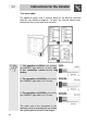
Instructions for the installer Twin oven model The appliance comes with a terminal board on the back for electrical hook-up (see following diagram). To open the terminal board cover, remove the fixing screw and raise the cover. 1 - For operation on 230V∼: use a three2 pole H05RR-F type cable (3 x 4 mm ). This is the connection carried out in the factory. 2 - For operation on 230V3N∼: use a four2 pole H05RR-F type cable (4 x 2.5 mm ).
Instructions for the installer 2.2 Ventilation requirements The room containing the appliance should have an air supply in accordance with B.S. 5440 part 2 1989. 1. All rooms require an opening window or equivalent, and some rooms will require a permanent vent as well. 3 2 2. For room volumes up to 5 m an air vent of 100 cm is required. 3. If the room has a door that opens directly to the outside, and the 3 room exceeds 1 m no air vent is required. 3 3 2 4.
Instructions for the installer 3. ADAPTATION TO DIFFERENT TYPES OF GAS Before performing any cleaning or maintenance work, detach the appliance from the electrical socket. The cooking hob of the cooker is preset for G20 natural gas at a pressure of 20 mbar. In the case of functioning with other types of gas the burner nozzles must be changed and the minimum flame adjusted on the gas taps. Replace the burner nozzles as indicated in the table of the gas to be used. 3.1 Changing nozzles 1. 2. 3.
Instructions for the installer 3.2 Burner and nozzle characteristics table Burner Auxiliary Semi rapid Rapid Triple crown Burner Auxiliary Semi rapid Rapid Triple crown Rated heating capacity (kW) 1.05 1.8 3.0 3.3 Rated heating capacity (kW) 1.05 1.8 3.0 3.
Instructions for the installer 4. FINAL OPERATIONS After replacing the nozzles, reposition the flame-spreader crowns, the burner caps and the grids. Following adjustment to a gas other than the preset one, replace the gas adjustment label fixed to the appliance with the one corresponding to the new gas. This label is in the packet together with the nozzles. 4.1 Adjustment of minimum for natural gas Light the burner and turn it to the minimum position .
Instructions for the user 5. DESCRIPTION OF CONTROLS 5.1 Front control panel All the cooker controls and commands are on the front panel. Single oven model Before using the oven check that the electronic programmer is showing the symbol (see paragraph “5.2.1 Clock adjustment”.
Instructions for the user OVEN THERMOSTAT KNOB Selection of cooking temperature is carried out by turning the knob clockwise to the required temperature, between 50° and 250°C. The tell-tale light comes on to indicate that the oven is warming up. When it goes out it means that the required temperature has been reached. Intermittent going on and off of the light means that oven temperature is being constantly maintained at the programmed level.
Instructions for the user Twin oven model Before using the main oven check that the electronic programmer is showing the symbol (see paragraph “5.2.1 Clock adjustment”. DESCRIPTION OF SYMBOLS FRONT RIGHT BURNER MAIN OVEN BACK RIGHT BURNER AUXILIARY OVEN GRILL BACK LEFT BURNER AUXILIARY OVEN VARIABLE GRILL FRONT LEFT BURNER COOKING HOB BURNER COMMAND KNOB The flame is lit by pressing the knob and turning it anticlockwise to maximum flame .
Instructions for the user Intermittent going on and off of the light means that oven temperature is being constantly maintained at the programmed level.
Instructions for the user 5.2 Electronic Programmer The programmer user instructions are valid only for the main oven. LIST OF FUNCTIONS MINUTE-COUNTER KEY COOKING TIME KEY END-OF-COOKING KEY DECREASE TIME KEY INCREASE TIME KEY 5.2.1 Clock adjustment When using the oven for the first time, or after a power failure, the display flashes regularly and indicates . Press the keys and at the same time the keys or : each single press changes the time by 1 minute either up or down.
Instructions for the user 5.2.2 Semiautomatic cooking Use this setting for automatic oven switch-off at the end of cooking time. ; keep the key By pressing key , the display lights up, showing pressed and at the same time, press keys or to set the cooking time. Release key to start the programmed cooking time count. The display will now show the right time together with symbols A and . 5.2.3 Automatic cooking Use this setting to automatically start and stop the oven.
Instructions for the user 5.2.5 Adjusting alarm volume The acoustic alarm has three different settings. These can be operated, while the alarm is sounding, by pressing key . 5.2.6 Switching off the alarm The alarm switches off automatically after seven minutes. They can be and together. manually de-activated by pressing the keys 5.2.7 Minute Counter The programmer can also be used as a simple minute counter. By ; keep the key pressed and at pressing key , the display shows the same time press keys or .
Instructions for the user 6. USE OF THE COOKING HOB 6.1 Lighting of the cooking hob burners Before lighting the hob burners check that the flame-spreader crowns are located in their housing with their respective caps. Ensure that flamespreader holes A correspond to the spark plugs and the thermocouples. Grid B should be used for Chinese wok type pans. Each knob corresponds to the burner indicated. The appliance is equipped with an electronic lighting device.
Instructions for the user 6.2 Practical advice for using the cooking hob burners For better use of the burners and lower gas consumption, use covered containers that are proportional in size to the burner to prevent the flame from licking the sides (see paragraph “6.3 Diameter of containers”). When water reaches the boiling point, lower the flame so that it doesn’t overflow. To avoid burns or damage to the hob, all recipients or griddle plates must be placed within the perimeter of the cooking hob.
Instructions for the user 8. AVAILABLE ACCESSORIES The main oven has 4 support for positioning plates and racks at various heights and has upper protection. The auxiliary oven has 2 support. Oven grill: for cooking food on plates, small cakes, roasts or food requiring light grilling. Plate grill: for placing above plate for cooking foods that might drip. Oven plate: useful for catching fat from foods on the grill above. Pastry plate: for baking cakes, pizza and oven desserts.
Instructions for the user 9. COOKING HINTS During cooking, do not cover the bottom of the oven with aluminium or tin foil and do not place pans or oven trays on It as this may damage the enamel coating. If you wish to use greaseproof paper, place it so that it will not interfere with the hot air circulation inside the oven. In fan-assisted mode preheating should be carried out at 30/40°C above the cooking temperature.
Instructions for the user 9.2 Hot-air grilling FUNCTION SWITCH THERMOSTAT SELECTOR FROM 50° TO 230°C SWITCH VARIABLE GRILL CHOICE BETWEEN MIN. AND MAX. FUNCTION SWITCH THERMOSTAT SELECTOR FROM 50° TO 250°C SWITCH Ensures uniform heat distribution with greater heat penetration into the food. Food will be lightly browned on the outside and remain soft inside. Keep the oven door closed during cooking. Heating up time must not exceed 60 minutes. 9.
Instructions for the user 9.4 Defrosting FUNCTION SWITCH THERMOSTAT IN POSITION “0” THERMOSTAT IN POSITION The flow of air produced by the fan ensures quicker defrosting. The air circulating inside the oven is at room temperature. The advantage of defrosting at room temperature is that it does not alter the taste and appearance of the food. 9.
Instructions for the user This traditional cooking method, in which heat comes from above and below, is suitable for cooking food on a single level. You have to preheat the oven until the set temperature is reached. Place the food in the oven only after the thermostat indicator light has turned off. very fatty meats may be put in when the oven is still cold. Put frozen meat in immediately, without waiting for it to thaw.
Instructions for the user Permits rapid browning of foods. You are advised to place the pan in the highest guide. For short-term cooking of small quantities, place the grid in the third guide from the bottom. For long-term cooking and grills, put the grid in the lowest guide in accordance with the size of the pieces. Make sure that the oven door is closed during cooking. FUNCTION SWITCH VARIABLE GRILL CHOICE BETWEEN MIN. AND MAX.
Instructions for the user This type of cooking is only for the main oven. Use it for small size pieces. Prepare the food on the spit rod and block fork screws A. Insert the frame B in the third level from the bottom. Remove handle D and position the spit rod so the pulley E remains guided on frame B. Completely fit frame B until the tip of the spit rod fits into hole C on the back wall of the oven. Place an oven dish F on the bottom guide and pour in a little water to prevent smoke from forming.
Instructions for the user 10. CLEANING AND MAINTENANCE 10.1 Cleaning stainless steel To keep stainless steel in good condition it should be cleaned regularly after use. Let it cool first. Always disconnect the electricity supply before cleaning the appliance. 10.1.1 Ordinary Daily Cleaning To clean and preserve the stainless steel surfaces, always use only specific products that do not contain abrasives or chlorine-based acids.
Instructions for the user 10.2.3 Ignition plugs and thermocouples To work well, the ignition plugs and thermocouples must always be very clean. Check them frequently and clean them with a wet rag if necessary. Any dry residue should be removed with a toothpick or a needle. 10.3 Cleaning the inside of the oven For best oven upkeep clean regularly after having allowed to cool. Take out all removable parts. Clean the oven grill and side guides with hot water and non-abrasive detergent. Rinse and dry.
Instructions for the user 10.3.4Assembling the self-cleaning liners 1. Remove all accessories from the oven; 2. Remove the side grilles (fig.1); 3. Extract the side liners “F” and “G”(fig. 2); 4. Remove the back panel “A” after undoing the threaded ring-nut “C” (fig. 2). 5. Reassemble the panels, restoring them to their original position. 1) 2) 10.4 Door glass These should always be kept very clean.
Instructions for the user 11. EXTRAORDINARY MAINTENANCE Ovens periodically require small maintenance interventions or replacement of parts subject to wear and tear such as gaskets, electric bulbs etc. Specific instructions for each intervention of this type appear below. Before performing any operations requiring access to powered parts, switch off the power supply to the machine. 11.
Instructions for the user 11.2 Dismantling of the doors Hold the door on both sides with both hands near hinges A and raise levers B. Lift up the door forming an angle of about 45° and remove. To refit, slide the hinges A in the grooves, drop the door and release levers B. 11.3 Oven door gaskets The door gaskets can be dismantled for thorough cleaning of the ovens. Before removing the gaskets the oven doors must be removed as previously described.