
Range Instructions for Installation and Use


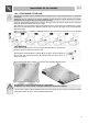

Table Of Contents
- 1. INSTRUCTIONS FOR PROPER USE
- 2. SAFETY INSTRUCTIONS
- 3. KNOW YOUR HOB
- 4. BEFORE FIRST USE
- 5. COOKING ZONES
- 6. DESCRIPTION OF CONTROL ON THE FRONT CONTROL PANEL
- 7. USE OF THE COOKING HOB
- 7.1 Hobs with knobs
- 7.2 Hobs with touch-control buttons
- 7.2.1 Switching on the hob
- 7.2.2 Single cooking zones
- 7.2.3 Dual cooking zones
- 7.2.4 Triple cooking zones
- 7.2.5 Heating zone
- 7.2.6 Cooking zone lock-out
- 7.2.7 Cooking zone layout
- 7.2.8 Timer (on some models only)
- 7.2.9 Modifying the data set
- 7.2.10 Residual heat
- 7.2.11 Control circuit board thermal protection
- 7.2.12 Operator Error
- 7.2.13 Switching off the cooking zones
- 7.2.14 Switching off
- 7.3 Cooking tips
- 7.4 Holding function “A”
- 8. CLEANING AND MAINTENANCE
- 9. SOMETHING WRONG?
- 10. INSTALLATION
Instructions for the installer
30
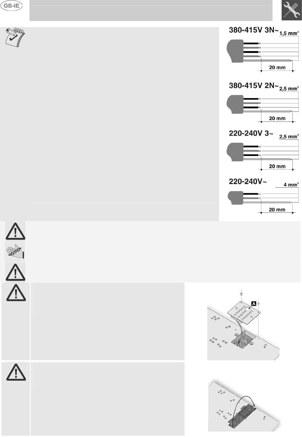
For operation on 380-415 V 3N
∼
: use an - H05V2V2-F type five-core
cable (5 x 1,5 mm
2
).
For operation on 380-415 V 2N
∼
: use an - H05V2V2-F type four-core
cable (4 x 2,5 mm
2
).
For operation on 220-240 V 3
∼
: use an - H05V2V2-F type four-core
cable (4 x 2,5 mm
2
).
For operation on 220-240 V
∼
: use an - H05V2V2-F type three-core
cable. (3 x 4 mm
2
: hob with 5 cooking zones)
The cable end to be connected to the appliance must be provided with
an earth wire (yellow-green) at least 20 mm longer.
READ THE CONNECTION LAYOUT PLATE UNDERNEATH THE APPLIANCE WITH CARE.
If the appliance you have purchased is not fitted with a mains power lead a power lead
resistant to a temperature of at least 90°C must be used.
Otherwise, the electrical safety of the appliance may be put at risk.
The manufacturer declines all responsibility for damage to persons or things caused by non-
observance of the above prescriptions or by interference with any part of the appliance.
Warning: pass the power cable through hole “A” and fit
the cable clamp plate after making the electrical
connection.
To fit the plate, simply use the provided bolts to secure it
under the casing as shown in the figure.
TYPE 1 TERMINAL BOARD
Warning: close the cable clamp after making the
electrical connection. Close the terminal board cover by
twisting it down.
TYPE 2 TERMINAL BOARD